00196497-07_SM_SXDX12_en.pdf - 第314页
Description of the Circuit Boards Gantry 5.2.2 Vision board spread spectru m HCU1 [03067289-xx] 314 Service Manual SIPLACE SX1/SX2/DX1/DX2 FS02 5.2.2 5 . 2 . 2 V is io n b o a r d s p r e a d s p e c t r u m H C U 1 [ 0 …
Description of the Circuit Boards
5.2.1 Head Interface C700B [03055072-xx] Gantry
Service Manual SIPLACE SX1/SX2/DX1/DX2 FS02 313
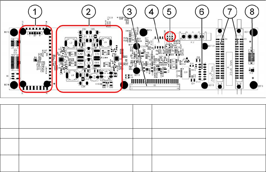
Head interface C700
(1) Powercube X7 24V (input 40V) (2) DC/DC converter +15 V, -15 V, +5 V,
+3.3 V, +1.5 V (input 24 V from power
cube)
(3) X6 – connection for basic adapter board (4) DIP switch S1
(5) LEDs H2 to H4 (6) X15 – Connection for incremental encoder
(old)
(7) X3, X4 – connection for gantry interface (8) X5 – connection for vision board (CAN_H/
L)
Description of the Circuit Boards
Gantry 5.2.2 Vision board spread spectrum HCU1 [03067289-xx]
314 Service Manual SIPLACE SX1/SX2/DX1/DX2 FS02
5.2.2
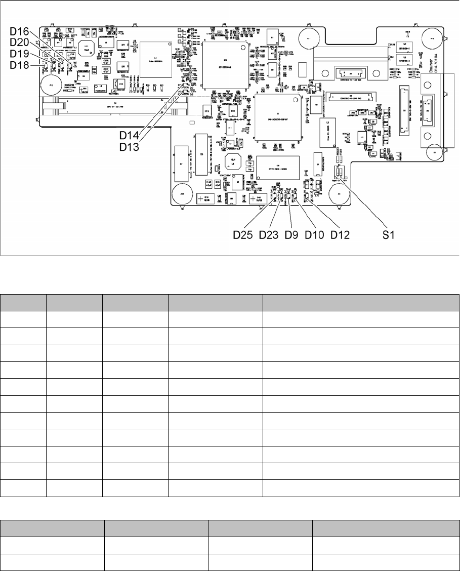
5.2.2 Vision board spread spectrum HCU1 [03067289-xx]
Vision board spread spectrum HCU1 [03067289-xx]
03067289-02
LED [03067289-02]
Dip switch S1 [03067289-02]
All switches must be set to OFF. If required, the CAN controller can be reset with the reset switch.
LED Color Status Signal name Description
D9 GN ON LED_XC_OK RUN
D10 RD ON LED_XC_ERR ERROR
D12 RD ON XC_RESET RESET
D13 GN ON IO/LVDS51P CO camera active
D14 GN ON IO/LVDS51N PCB camera active
D16 GN ON P12VCAM_I +12VDC for camera
D18 GN ON P5VCAM +5VDC for camera
D19 GN ON P2.5VCAM + 2.5 VDC for camera
D20 GN ON P3.3VCAM + 3.3VDC for camera
D23 GN ON P5V +5VDC
D25 GN ON P15V +15VDC
Switch Status Signal name Description
S1.1 OFF HW_RESET ON: RESET CAN controller
S1.2 OFF CAN_ID Not used
Description of the Circuit Boards
5.2.2 Vision board spread spectrum HCU1 [03067289-xx] Gantry
Service Manual SIPLACE SX1/SX2/DX1/DX2 FS02 315
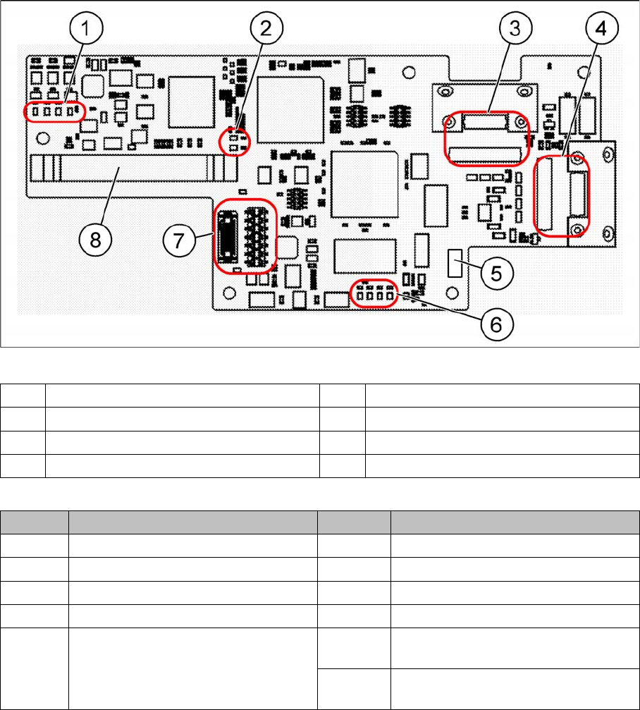
Previous function states
03067289-01
LED [03067289-01]
The voltage monitors trigger as soon as the nominal voltage is undershot by 5%.
(1) LEDs – voltage monitoring (2) LEDs – cameras
(3) X1, X5 – PCB camera (4) X2, X6 – CO camera
(5) DIP switch S1 (6) LEDs
(7) X7 – connecting C700 (8) X4 – connecting the trailing cable
LED Description LED Description
15V Is generated from 24 V 5V Voltage monitoring
5V Is generated from 24 V 2.5V Voltage monitoring
RUN Flashes when everything is OK 3.3V Voltage monitoring
ERROR Lights up when an error occurs 12V Voltage monitoring
RESET Lights up when the reset switch on the
DIP switch S1 has been set.
C 1 Lights up when the CO camera is ac-
tive
C2 Lights up when the PCB camera is ac-
tive