Specification_SIPLACE_F5_eng.pdf - 第10页
9 Description Full Flip Ch ip h andling capab ility on the part of the SIPLACE F 5 is en- sured by a flux dispenser installed directly next to the revol ver head. Immediately before the placement head places the Flip Ch …
8
Description
6
66
6-
--
-N
NN
No
oo
ozz
zzzz
zzl
ll
le
e e
e R
RR
Re
ee
ev
vv
vo
oo
ol
ll
lv
vv
ve
ee
er
r r
r H
HH
He
ee
ea
aa
ad
dd
d
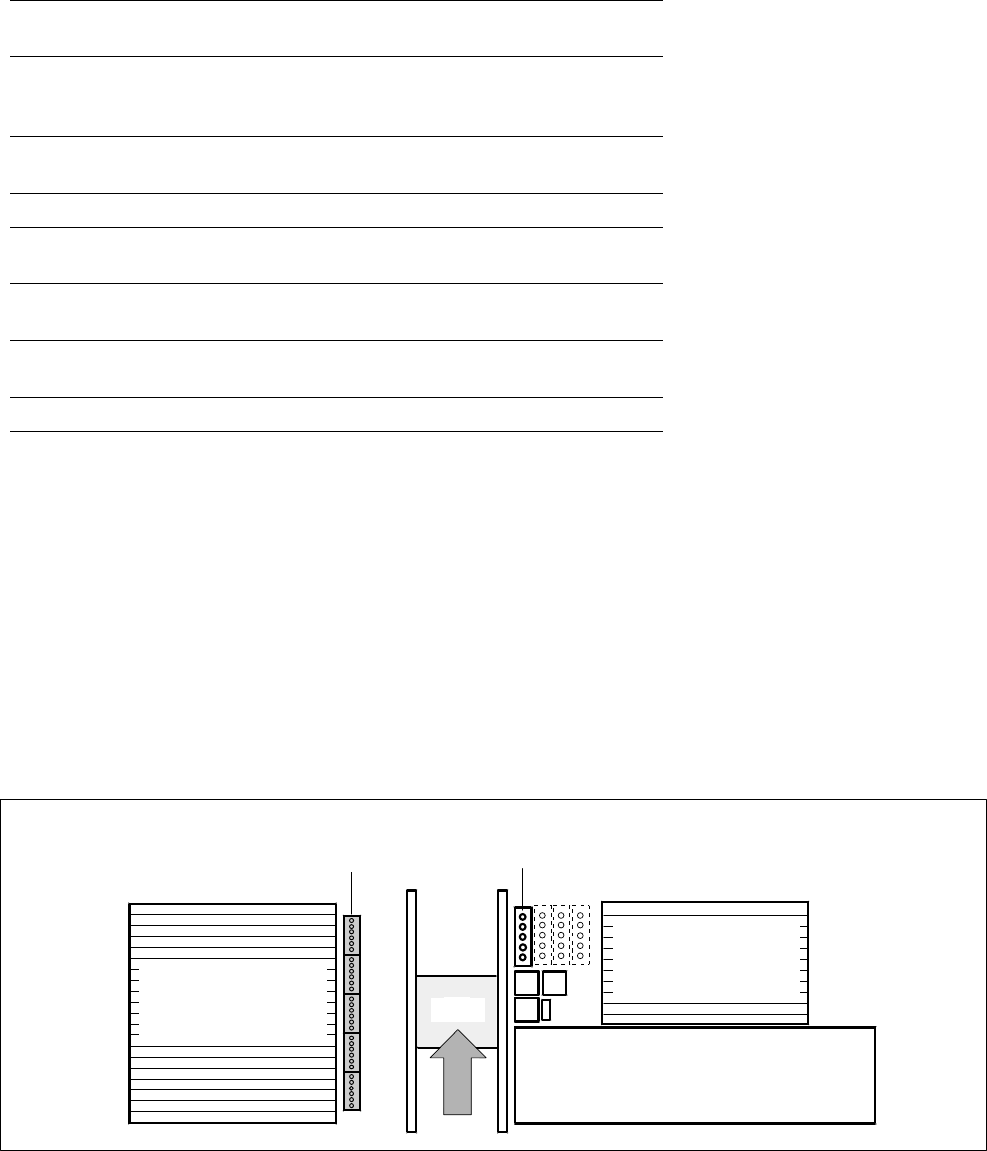
A nozzle changer for the 6-nozzle
revolver head can be installed to
the left of the PCB conveyor with
no loss of feeder locations. It will
change the set-up of the place-
ment head quickly and reliably for
the specific nozzle configuration
valid for a job. Damaged or faulty
nozzles can be exchanged via the
menu function.
P
PP
Pi
ii
ic
cc
ck
k k
k &
& &
& P
PP
Pl
ll
la
aa
ac
cc
ce
e e
e H
HH
He
ee
ea
aa
ad
dd
d
SIPLACE F
5
is equipped with a
nozzle changer for the Pick & Place
Head. As standard, it is fitted with
one magazine. This can simultane-
ously hold 4 standard nozzles and
one special nozzle. The changer is
mounted on the right-hand side of
the PCB conveyor with no loss in
feeder locations. As an option, 3
additional nozzle magazines can be
installed for 5 nozzles each. Noz-
zles are exchanged automatically
during the placement sequence.
Placement Heads:
Nozzle Changer
Technical Data
6-Nozzle Revolver Head
Type of nozzle
All standard nozzles of nozzle series 7xx
and 8xx
(special nozzles must be tested individually)
Capacity
5 magazines, each with 6 nozzles of one
nozzle series
Nozzle changing times About 2 s per nozzle
Pick & Place Head
Type of nozzle
All standard nozzles of nozzle series 4xx
(special nozzles must be tested individually)
Capacity
1 to 4 magazines each with 5 nozzles of
one nozzle series
Nozzle changing times About 2 s per nozzle
Position of Nozzle Changers
Waffle Pack Changer (Option)
Component Feeders
for Revolver Head /
Pick & Place Head
Component Feeders
for Revolver Head /
Pick & Place Head
PCB
Nozzle Changer for the
6-Nozzle Revolver Head Nozzle Changer Pick & Place Head for 5 Nozzles
Each with 5 Magazines for 6 Nozzles (Option) (Option: + 3 Nozzle Changers Each for 5 Nozzles

9
Description
Full Flip Chip handling capability on
the part of the SIPLACE F
5
is en-
sured by a flux dispenser installed
directly next to the revolver head.
Immediately before the placement
head places the Flip Chip, the
mounting location on the PCB is
wetted with low-viscosity flux by
means of a dispensing needle.
The flux dispenser option essen-
tially comprises one stepping mo-
tor with piston, injector and valve
to change the operating mode (fill /
dispense injector) plus one storage
tank. The stepping motor positions
the piston over the storage tank to
be filled or over the Flip Chip
mounting location on the PCB for
emptying.
The purpose of a programmable
waiting time until PCB transport is
to allow the low-viscosity flux suf-
ficient time to dry so that the Flip
Chip(s) will not shift position while
the PCB is being moved out. A
new PCB conveyor control with
adjustable acceleration and delay
ramps makes programming the
waiting time largely superfluous.
Placement Heads:
Flux Dispenser for Full Flip Chip Capability (Option)
Technical Data
Programmable amount 2 µl to 100 µl
Smallest application incre-
ment
1 µl
Content of syringe 1 ml
Content of flux reservoir 100 ml
Volume to be applied at the
mounting location
Varies by Flip Chip size as well as wetting
properties of flux and substrate material
Flip Chip down holding time
after placement 0 to 5 s
Increment down holding
time
0.01 s
Minimum waiting time prior
to PCB transport 0 to 40 s
Increment waiting time 1 s
Dispensing cycle time 1.5 s including positioning
Rinse cycle 1 to 10 x contents of syringe
Filling level 1 Warning
Filling level 2 Empty (causes machine stop)
Accuracy of dispenser
needle positioning
± 0.05 mm
10
Description
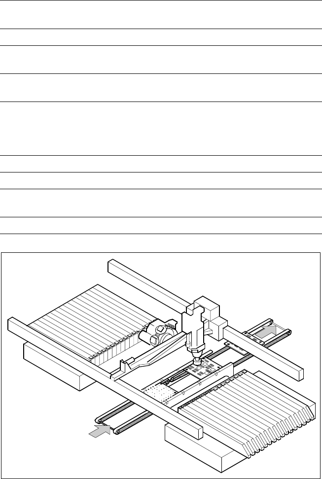
On SIPLACE F
5
the in-line con-
veyor system guarantees a quick
adjustment to new PCB widths.
The change is made either at the
station via menu function or from
the line computer via the auto-
matic width adjustment unit. Ce-
ramic substrates are also trans-
ported and, if necessary, fastened
in place via the optional ceramic
substrate centering unit.
As standard, the SIPLACE place-
ment systems are available with a
single conveyor system.
PCB Conveyor:
Single Conveyor
Technical Data
PCB dimensions
50 x 50 mm to 460 x 460 mm
(optional 460 x 508 mm)
PCB thickness 0.5 to 4.5 mm
Max. PCB warpage
Top: 4.5 mm - PCB thickness
Bottom: 0.5 mm + PCB thickness
PCB underside clearance
Standard: 25 mm,
Option: max. 40 mm
PCB conveyor height
830 ± 15 mm (Standard)
900 ± 15 mm (Option)
930 ± 15 mm (Option)
950 ± 15 mm (Option) SMEMA
Fixed conveyor edge On right (standard); on left (option)
Type of interface Siemens (standard); SMEMA (option)
Component-free PCB
handling edge 3 mm
PCB changing time 2.5 s
PCB Conveyor
PCB
Transport Direction