Specification_SIPLACE_F5_eng.pdf - 第21页
20 Description If a number of Waffl e Packs are required during a placement proc- ess, it is advis able to utilize the automatic magazine c hange with the help of the Waffle Pack Changer. The s et-up of the Waffle Pack C…

19
Technical Data
Tape size: Combimodule 8 / 12 / 16 mm
Recommended Bare Die size:
8 mm Surf Tape:
1 x 1 mm up to 2.3 x 2.3 mm
12 mm Surf Tape:
2.3 x 2.3 mm up to 5 x 5 mm
16 mm Surf Tape:
3.8 x 3.8 mm up to 9.5 x 9.5 mm
Component positional
requirements:
Size of Bare Die ≤ 2.3 x 2.3 mm:
± 100 µm / 6 σ
Size of Bare Die ≥ 2.3 x 2.3 mm:
± 200 µm / 6 σ
(in relation to center of pocket)
Min. space between tape pocket
web and edge of die:
0.4 mm (0.015 mil)
Tape specification:
IEC 286-3, DIN-IEC-286, EIA 481 und
JIS C 0806
Tape reel diameter: 7" or 15" (178 or 381 mm)
Feeder space 1 slot
Description
The Surf Tape feeder is a specific
module for the placement of Bare
Dies. The feeding technology is
different to a standard feeder and
requires e.g. a poke-up needle and
therefore a special know how.
The Surf Tape feeder is offered as
a combi module for 8 / 12 / 16 mm
Surf Tape material. To switch from
one tape size to the other is done
very easily by changing only three
parts which are included.
The feeding process starts with
the transport of the bare die to the
pick up position. This position is
exactly defined by a sensor. The
nozzle moves onto the bare die
and the vacuum is activated. A
poke-up needle moves up and lifts
up the bare die and the nozzle. At
the same time the Surf Tape starts
to loose contact with the bare die.
When there is no contact between
the tape and the bare die the noz-
zle moves upwards and the poke-
up needle downwards. The re-
quired time for this process de-
pends on different items like stor-
age time of the tape, size of the
bare die etc. and is adjustable.
Component Supply:
Surf Tape Feeder for Bare Dies
20
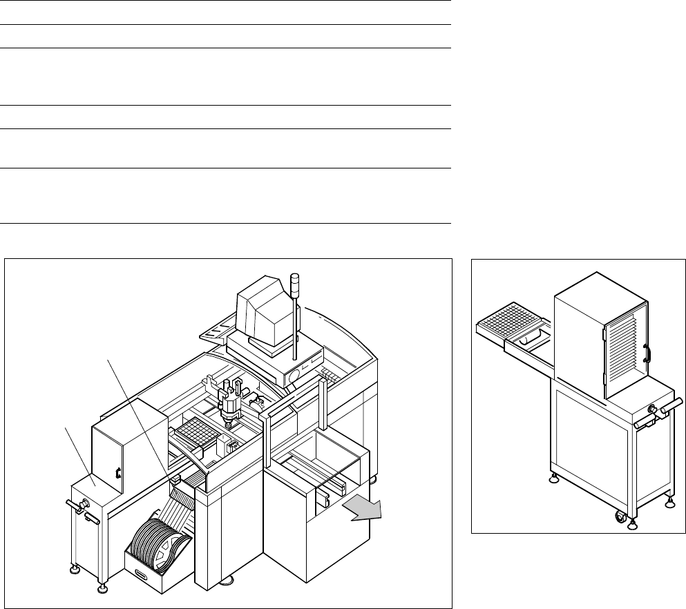
Description
If a number of Waffle Packs are
required during a placement proc-
ess, it is advisable to utilize the
automatic magazine change with
the help of the Waffle Pack
Changer. The set-up of the Waffle
Pack Changer is exactly coordi-
nated with the sequence of
placement for a work process op-
timized in terms of path and time.
An elevator automatically brings
the correct magazine into the ac-
cess range of the placement head.
The magazine for the first compo-
nent is changed as soon as a PCB
moves into the placement
A narrow component table with 10
locations for feeder modules is
also available on the tray changer
(sample capacity: 20 tracks of
8 mm each).
Component Supply:
Waffle Pack Changer (Option)
Technical Data
Contents of storage 28 carrier trays for Waffle Packs
Max. magazine size 240 x 340 mm
Max. tray size
Pick & Place Head
6-Nozzle Revolver Head
≤ 240 x 340 mm
≤ JEDEC Tray
Magazine height 15 mm including component
Max. number of
component types 200 per Waffle Pack Changer
Changing time
per magazine
< 3 s
parallel to other substeps during a
placement cycle
SIPLACE F
5
with Waffle Pack Changer
Waffle Pack Changer
10 Feeder Positions
Waffle Pack
Changer
PCB
Transport
Direction
conveyor and valid data for cluster
and set-up are available. The re-
maining magazine changes are
made in slack time during place-
ment. The magazines can be re-
plenished without any machine idle
time. The placement head puts
faulty components back where it
picked them up.
21
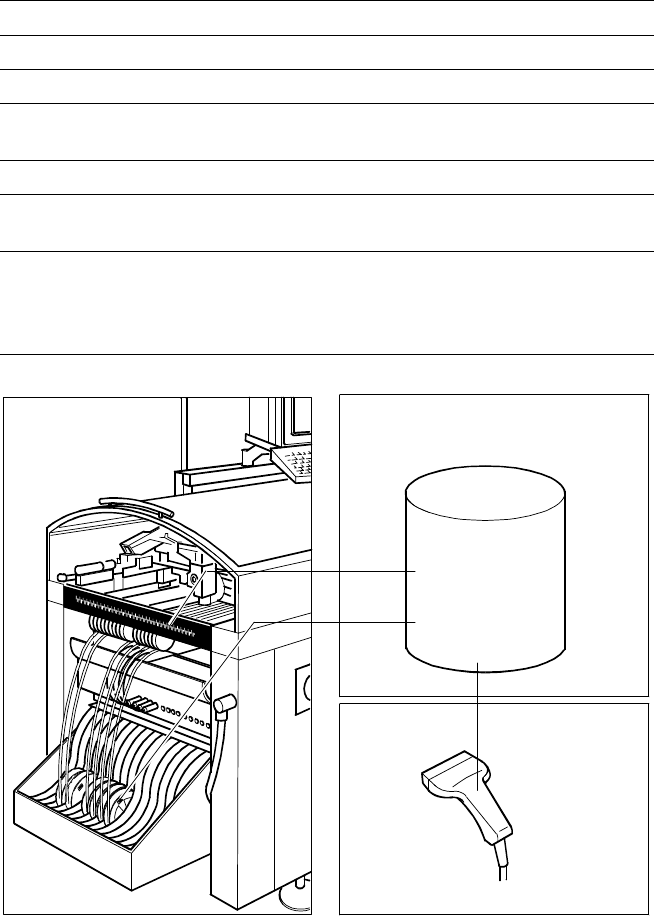
Description
The bar code scanner enables a
speedy and reliable check of set-
up and refill. To this end the bar
codes of the tracks (on the track
scale on the component table) and
the loaded components assigned
to the tracks (bar code labels on
tapes, Bulk Cases, etc.) are read in
with a hand scanner. An audible
and optical signal acknowledges a
successful reading operation. If the
label is damaged the bar can also
be entered at the keyboard.
The allocation of the components
to their respective track is de-
scribed in the set-up data. An error
message is displayed if the data
received from the bar code scan-
ner does not conform with the set-
up data.
If the set-up check is switched on,
it becomes a mandatory step in
the set-up process. If it is
switched off the set-up check is
optional.
Component Supply:
Component Bar Code Scanner for Set-Up and Refill Check
(Option)
Technical Data
Connection Station computer
Data input Bar code scanner or keyboard
Max. number of characters 40
Restrictions
Bar codes beginning with number 1 or 2
or with less than 5 characters
Number of bar codes 6 per component
Number of filters
to extract relevant data 1 per bar code
Preset code types
Code 39 (standard or full ASCII),
Code 2 from 5 interleaved and normal,
Code 128, UPC/EAN/JAN codes
(more on request)
The scanner checks the corresponding track and
the components
Component
Control
Set-Up File
Track Bar Code
Scanner
Component
Bar Code