Specification_SIPLACE_F5_eng.pdf - 第12页
11 Description Thanks to reduced non-productive times the dual PCB co nveyor can substantially i ncrease the through- put, depending on the progr am. It makes i t possible to transport two PCBs through the pl acer simult…
10
Description
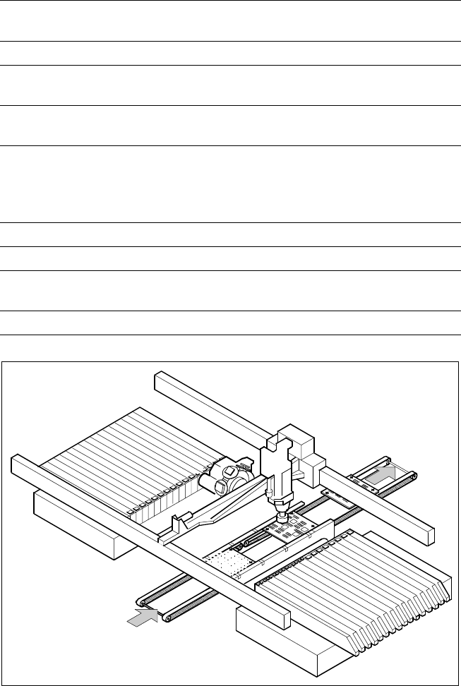
On SIPLACE F
5
the in-line con-
veyor system guarantees a quick
adjustment to new PCB widths.
The change is made either at the
station via menu function or from
the line computer via the auto-
matic width adjustment unit. Ce-
ramic substrates are also trans-
ported and, if necessary, fastened
in place via the optional ceramic
substrate centering unit.
As standard, the SIPLACE place-
ment systems are available with a
single conveyor system.
PCB Conveyor:
Single Conveyor
Technical Data
PCB dimensions
50 x 50 mm to 460 x 460 mm
(optional 460 x 508 mm)
PCB thickness 0.5 to 4.5 mm
Max. PCB warpage
Top: 4.5 mm - PCB thickness
Bottom: 0.5 mm + PCB thickness
PCB underside clearance
Standard: 25 mm,
Option: max. 40 mm
PCB conveyor height
830 ± 15 mm (Standard)
900 ± 15 mm (Option)
930 ± 15 mm (Option)
950 ± 15 mm (Option) SMEMA
Fixed conveyor edge On right (standard); on left (option)
Type of interface Siemens (standard); SMEMA (option)
Component-free PCB
handling edge 3 mm
PCB changing time 2.5 s
PCB Conveyor
PCB
Transport Direction
11
Description
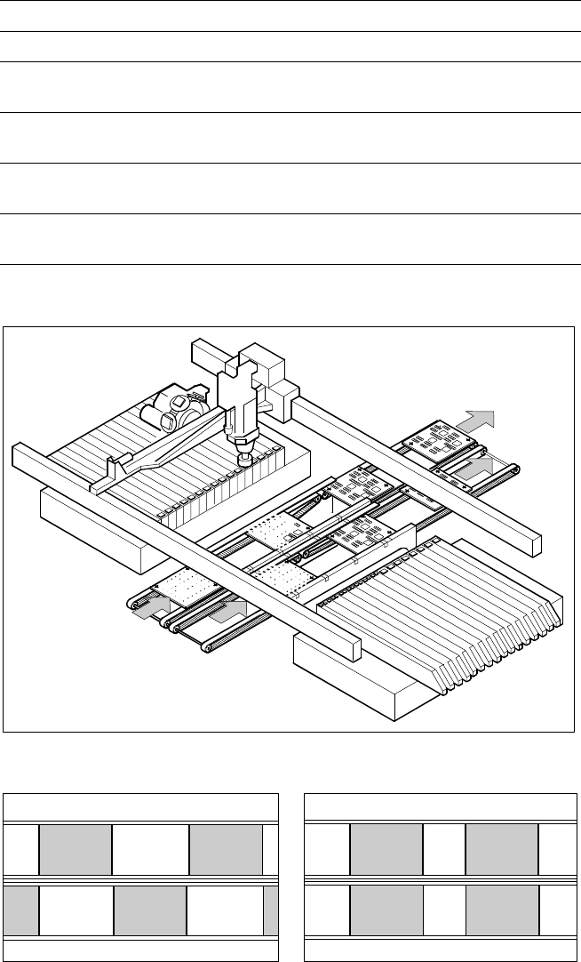
Thanks to reduced non-productive
times the dual PCB conveyor can
substantially increase the through-
put, depending on the program. It
makes it possible to transport two
PCBs through the placer simulta-
neously (synchronous) or alter-
nately (asynchronous).
In the synchronous type of trans-
port it is possible, for example, to
finish the top and bottom of the
PCB in a single line without using
cluster technology.
In the asynchronous type of trans-
port a PCB is moved into the
placer in “slack time” while an-
other of the same type is being
populated. The non-productive
time caused by the PCB transport
is therefore completely eliminated.
The increase in placement speed
to be anticipated is between 10
and 30%, depending on the com-
ponents to be placed on the PCB.
The client can switch between
asynchronous and synchronous
dual conveyor with little effort. The
optional ceramic substrate center-
ing is possible, but the PCB bar
code reading process is not.
PCB Conveyor:
Dual Conveyor
Technical Data
PCB dimensions 50 x 50 mm to 460 x 216.5 mm
Fixed conveyor edge Right (standard), left (option)
Placement program per conveyor
Synchronous: same or different
Asynchronous: same
PCB width
per conveyor
Synchronous: same or different
Asynchronous: same
Ink spot recognition
Synchronous: not possible
Asynchronous: same
Automatic width adjustment
Synchronous: not possible
Asynchronous: possible
Asynchronous Dual Conveyor
Asynchronous Synchronous
12
Description
Due to the increasing use of ce-
ramic substrates in Flip Chip tech-
nology the demands for precise
substrate centering are growing.
The optical and mechanical ce-
ramic substrate centering units on
SIPLACE 80 S-20, SIPLACE 80 F
4
and SIPLACE F
5
placement sys-
tems satisfy these demands.
Like the PCB vision module, opti-
cal centering is conducted with the
aid of reference marks (fiducials).
Depending on the contrast ratio
the machine activates the standard
lighting or the oblique lighting con-
tained in the option:
On ceramic and CM blue light
(Item No 116172).
On flexible PCBs using vision
module without IF-filter infrared
light (Item No 116173).
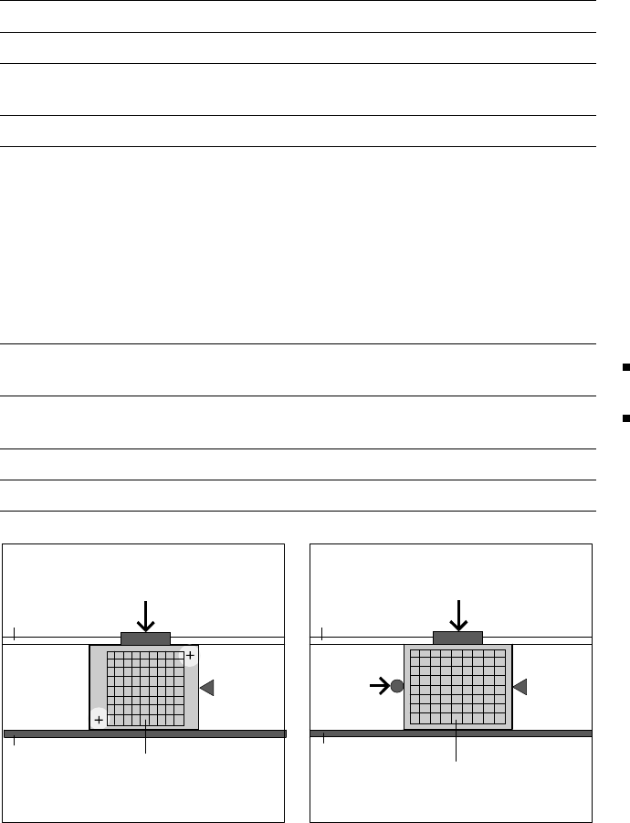
In certain cases, mechanical cen-
tering is required, e.g., when
placement is to continue to the
substrate edge, when handling of
the edges of the substrate is to be
particularly gentle, or when sub-
strates are scribed. In this gentle,
bounce-free procedure, the sub-
strate is fixed in place in the Y-
direction between a stop rail and a
rocking lever pneumatically cen-
tered in the X-direction.
PCB Conveyor:
Ceramic Substrate Centering (Option)
Technical Data
Substrate dimensions 2" x 2" to 4" x 7"
Substrate thickness 0.5 to 1.5 mm
Substrate model
Unscribed (no difficulty)
Scribed (after test)
Contact in conveyor 2.5 mm
Optical centering:
Field of view of the PCB
vision module
Type of lighting
with light-colored pastes
with dark pastes and short dis-
tance to neighboring struc-
tures (>1 mm)
5.7 x 5.7 mm
PCB vision module (standard)
Oblique lighting (option)
Fiducal mark criteria
See PCB vision module position recog-
nition
Mechanical centering
X-/Y-centering accuracy
± 0.07 mm / 4 σ
PCB underside clearance 12 mm
Compressed air connection 5.5 bar
Optical Centering via Mechanical Centering
PCB Camera
Movable
Transport Side
Y-Fixation
Y-Fixation
Fixed
Transport
Side
Fixed
Transport
Side
Stopper
Stopper
Ceramic Substrate
Ceramic Substrate
Movable
Transport Side
X-Center-
ing