Specification_SIPLACE_F5_eng.pdf - 第20页
19 Technical Data Tape size: Combimodule 8 / 12 / 16 mm Recommended Bare D ie size: 8 mm Surf Tape : 1 x 1 mm up to 2.3 x 2.3 mm 12 mm Surf T ape: 2.3 x 2. 3 mm up to 5 x 5 mm 16 mm Surf T ape: 3.8 x 3. 8 mm up to 9.5 x …
18
Description
The manual tray change is one
possibility for picking up Waffle
Packs. A number of “manual
trays” are placed on the compo-
nent tables (right-hand table for
Fine Pitch components). The two
component changeover tables are
retained.
This option is recommended if
only a few component types are
supplied in the tray.
JEDEC trays can be directly
clamped. Therefore there are spe-
cial access times for the place-
ment heads.
Component Supply:
Manual Trays
Technical Data
Sizes
136 x 360 mm; requires 5 feeder
locations
260 x 360 mm; requires 9 feeder
locations
Max. tray height 12.5 mm including component
Parts
Manual tray
Carrier tray
JEDEC Waffle Packs
Directly in the manual tray
136 mm wide
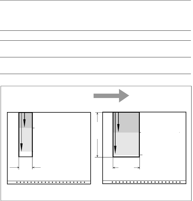
Pick & Place Head and Revolver Head Access to Manual Tray
Transport Direction
Revolver Head
Pick & Place Head
Feeder Table
Revolver Head
Pick & Place Head
Feeder Table
260
(136)
136
360
JEDEC Magazine Carrier Tray
119 mm
301 mm
157 mm
339 mm

19
Technical Data
Tape size: Combimodule 8 / 12 / 16 mm
Recommended Bare Die size:
8 mm Surf Tape:
1 x 1 mm up to 2.3 x 2.3 mm
12 mm Surf Tape:
2.3 x 2.3 mm up to 5 x 5 mm
16 mm Surf Tape:
3.8 x 3.8 mm up to 9.5 x 9.5 mm
Component positional
requirements:
Size of Bare Die ≤ 2.3 x 2.3 mm:
± 100 µm / 6 σ
Size of Bare Die ≥ 2.3 x 2.3 mm:
± 200 µm / 6 σ
(in relation to center of pocket)
Min. space between tape pocket
web and edge of die:
0.4 mm (0.015 mil)
Tape specification:
IEC 286-3, DIN-IEC-286, EIA 481 und
JIS C 0806
Tape reel diameter: 7" or 15" (178 or 381 mm)
Feeder space 1 slot
Description
The Surf Tape feeder is a specific
module for the placement of Bare
Dies. The feeding technology is
different to a standard feeder and
requires e.g. a poke-up needle and
therefore a special know how.
The Surf Tape feeder is offered as
a combi module for 8 / 12 / 16 mm
Surf Tape material. To switch from
one tape size to the other is done
very easily by changing only three
parts which are included.
The feeding process starts with
the transport of the bare die to the
pick up position. This position is
exactly defined by a sensor. The
nozzle moves onto the bare die
and the vacuum is activated. A
poke-up needle moves up and lifts
up the bare die and the nozzle. At
the same time the Surf Tape starts
to loose contact with the bare die.
When there is no contact between
the tape and the bare die the noz-
zle moves upwards and the poke-
up needle downwards. The re-
quired time for this process de-
pends on different items like stor-
age time of the tape, size of the
bare die etc. and is adjustable.
Component Supply:
Surf Tape Feeder for Bare Dies
20
Description
If a number of Waffle Packs are
required during a placement proc-
ess, it is advisable to utilize the
automatic magazine change with
the help of the Waffle Pack
Changer. The set-up of the Waffle
Pack Changer is exactly coordi-
nated with the sequence of
placement for a work process op-
timized in terms of path and time.
An elevator automatically brings
the correct magazine into the ac-
cess range of the placement head.
The magazine for the first compo-
nent is changed as soon as a PCB
moves into the placement
A narrow component table with 10
locations for feeder modules is
also available on the tray changer
(sample capacity: 20 tracks of
8 mm each).
Component Supply:
Waffle Pack Changer (Option)
Technical Data
Contents of storage 28 carrier trays for Waffle Packs
Max. magazine size 240 x 340 mm
Max. tray size
Pick & Place Head
6-Nozzle Revolver Head
≤ 240 x 340 mm
≤ JEDEC Tray
Magazine height 15 mm including component
Max. number of
component types 200 per Waffle Pack Changer
Changing time
per magazine
< 3 s
parallel to other substeps during a
placement cycle
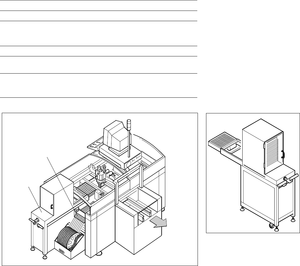
SIPLACE F
5
with Waffle Pack Changer
Waffle Pack Changer
10 Feeder Positions
Waffle Pack
Changer
PCB
Transport
Direction
conveyor and valid data for cluster
and set-up are available. The re-
maining magazine changes are
made in slack time during place-
ment. The magazines can be re-
plenished without any machine idle
time. The placement head puts
faulty components back where it
picked them up.