ts9800-user-guide-7511-0360_A.pdf - 第18页
18 6. HEATING 6 .1 Introduction The TS9800 Jet Valve with h ea t in g system is available for heating high vi scosity fluid. The hea ti ng system also helps to mainta in constant temperature. R eq uired parts: • TS9800 J…
17
The essential parameters are:
Parameter
Description
Rise Time
This is the time interval in which the valve is open.
The time increment is in 1 µs starting at 80 µs. The
maximum rising time is 1999 µs.
Open Time
This value defines the time in which the valve is
completely open. The value can be varied in steps of
1 µs. The minimum open time is 1 µs and the
maximum open time is 999999 µs.
Fall Time
During this time, the valve is closing and compressing
the media in the nozzle chamber. The time increment
is in 1 µs starting at 80 µs. The maximum falling
time is 1999 µs.
Delay Time
This is the time between two dispense pulses. It is
adjustable in 1 µs.
Percentage Lift (Lift
of Tappet)
This value corresponds to the stroke of the tappet. It is
entered in percent of the maximum stroke (100%).
Pulses
This value corresponds to the number of tappet stroke
per dispensing cycle in dot mode
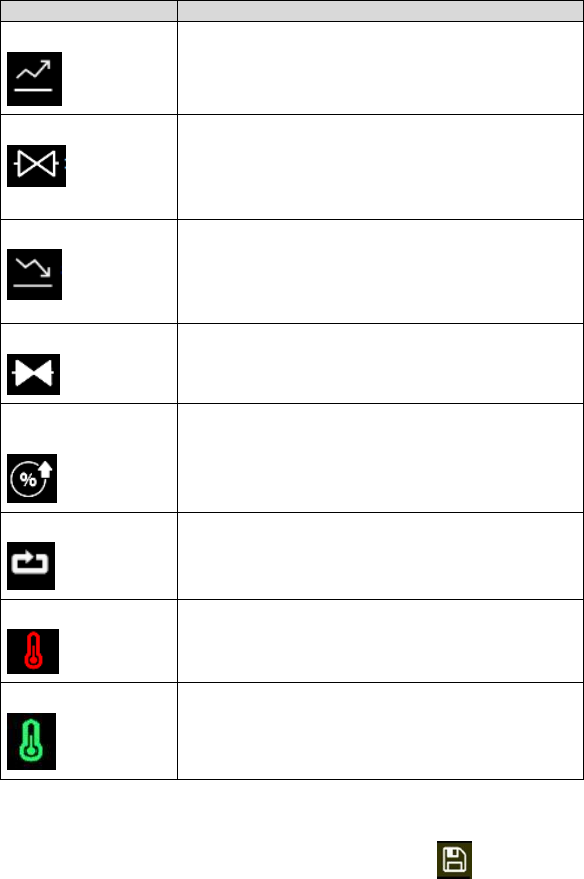
Heater OFF
This indicate the heater manifold is Off
Heater ON
This indicate the heater manifold is ON (temperature
range is from 0-90 degree C, click on value next to
icon to adjust setting)
After entering the dispensing parameters, touch ‘Save’ icon to save all the
parameters to the current program location. You can then start your dispensing
process. Note: For more detail on how to enter the dispensing parameters,
refer to section 9.5.3.
Table 1 – Essential parameters

18
6. HEATING
6.1 Introduction
The TS9800 Jet Valve with heating system is available for heating high
viscosity fluid.
The heating system also helps to maintain constant temperature. Required
parts:
• TS9800 Jet Valve with heater
• Heater Cable
6.2 Safety Instructions
• Use the Jet Valve with heating system should only be done by
trained staff.
• Carefully review the material safety data from the dispensing
material.
• Wear adequate protective clothing before starting to dispense
aggressive fluid.
• Be cautious that the media you want to dispense is applicable for
use with a heating system.
Warning:
• When using the Jet Valve with heater, please consult with the
material manufacture for proper operating temperature.
• Be aware of the exposed surface and fittings on the manifold. Do
not touch the heater without protective wear. Failure to do so can
result in serious burn and/or injuries.
6.3 Function
Resistance
All hydrous solvents (Media,
organic acid and base)
*Maximum heater setting value
90 °C
Supply Voltage
24 VDC
Power consumption
15 W
*Displayed temperature may not reflect the actual dispensed temperature.
19
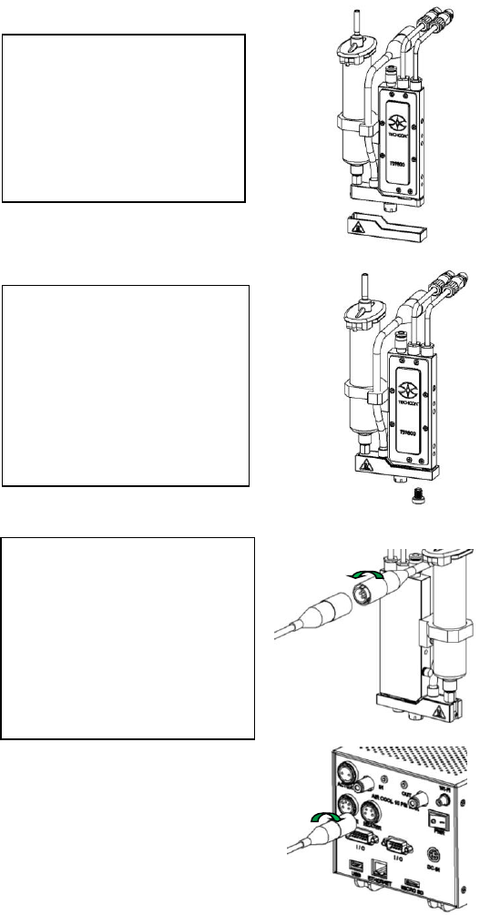
6.4 Mounting & Connection ( w/ Heater)
a
Step 1:
• Slide the heat guard over
the fluid manifold. The
alignment is done by the
nozzle adjustment nut and
the fluid manifold with
heating module.
Step 2:
• Use the 4mm hex wrench to
install the provided M6
screw from the bottom to
secure the heat guard in
place. Caution: Do not
over-tighten the screw since
it can damage the heat
guard.
Step 3:
• Connect the heater cable (4-
pins) from the valve’s
heating module to the
‘HEATER’ port of the
controller. Caution: After
connecting, tighten the
locking sleeve to secure the
connection.