00195427-02_AI_HeadReconfigKitsD1D2_DE+EN.pdf - 第59页
Assembly instructions Head Re configuration SIPLACE D 1 / D2 Edition 03/2007 57 2.7.3 Assembly of component camera st at. P&P (type 36) 32x32 digit al, at location 1 Use two set screws as a mounting aid for the ca ul…
Assembly instructions Head Reconfiguration SIPLACE D1 / D2
Edition 03/2007
56
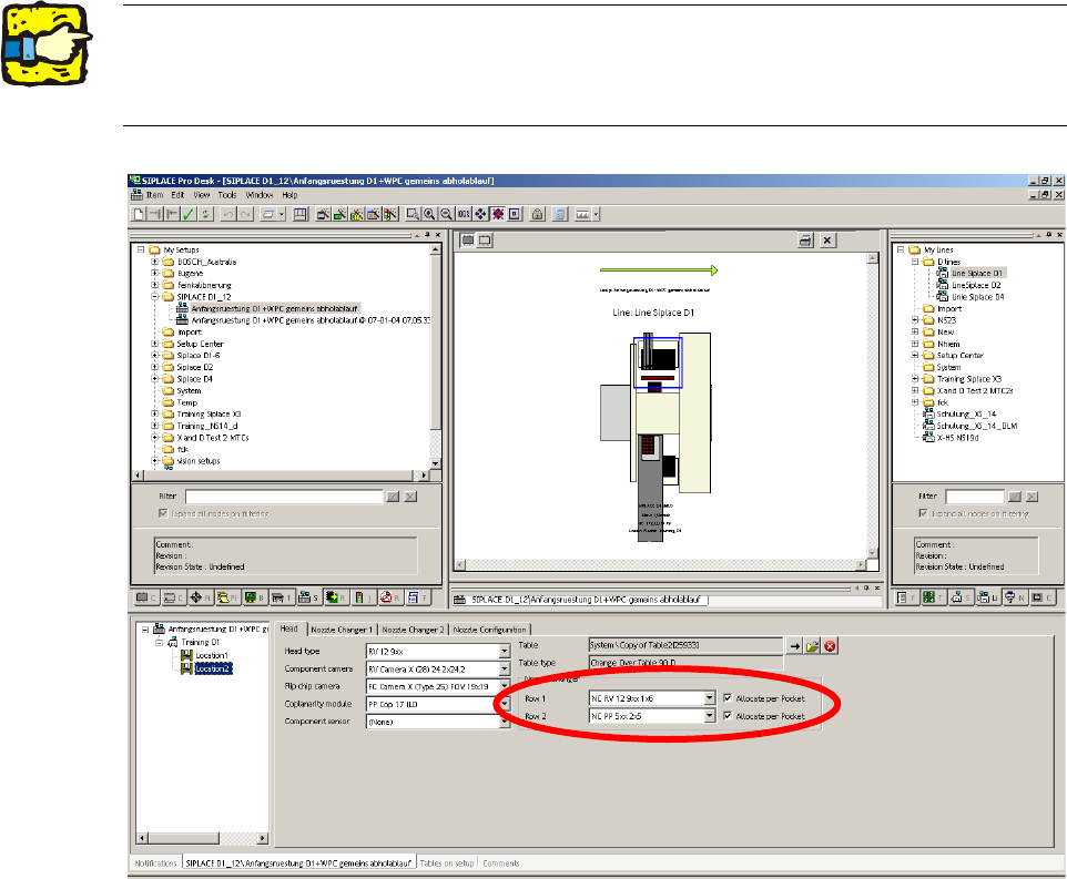
2.7.2 Configuring the P&P head with SIPLACE Pro
: Go to 'Setup editor' —'Location'—'head tab' and enter the C&P placement head.
2
2
: Reoptimize the set-up in SIPLACE Pro.
2The nozzle changer for the P&P head must be configured as row 2 at location 2. 2
For a D1S (with C&P placement head) for a location without placement head, "none" must be
entered for head type and nozzle changer. 2
Assembly instructions Head Reconfiguration SIPLACE D1 / D2
Edition 03/2007
57
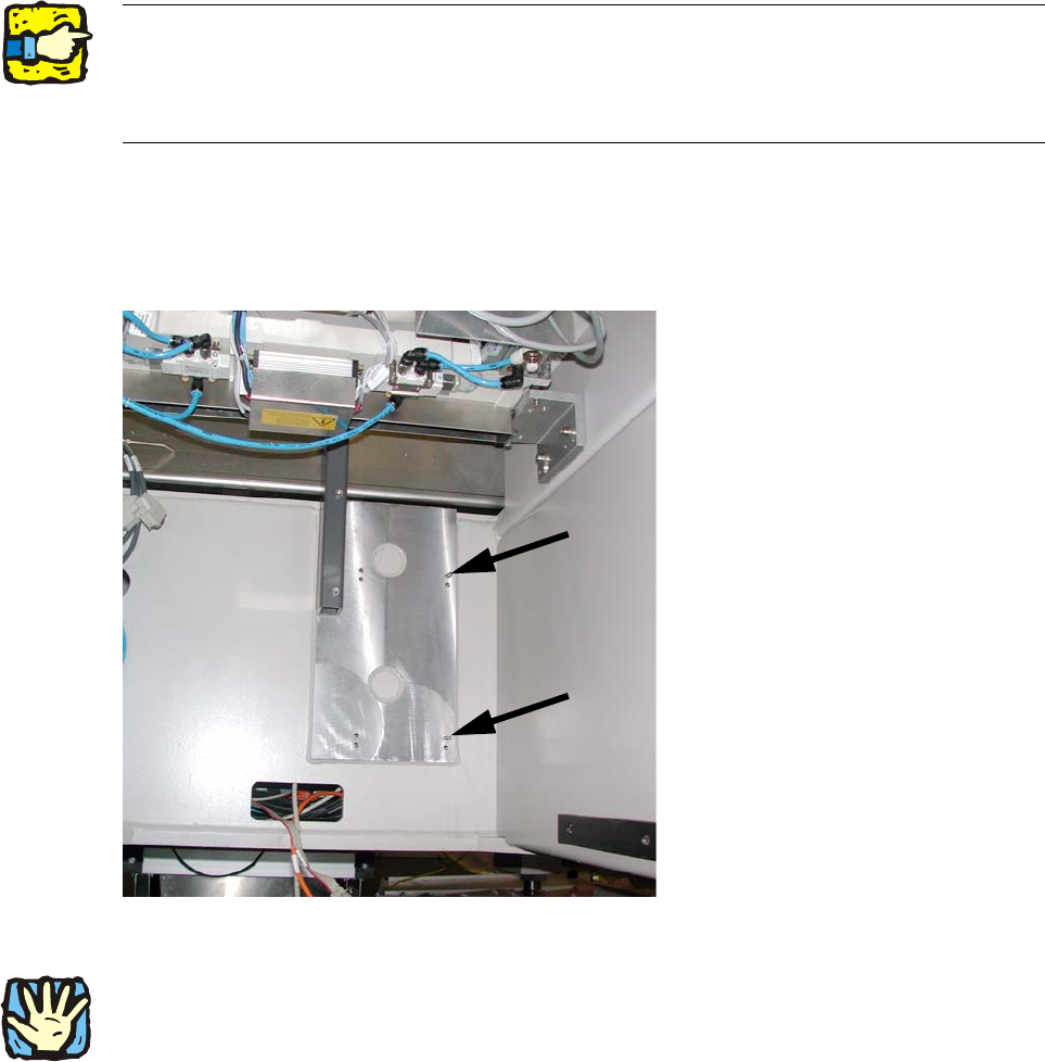
2.7.3 Assembly of component camera stat. P&P (type 36) 32x32 digital,
at location 1
Use two set screws as a mounting aid for the caul (supporting plate for camera calibration) for
mark and camera base.
The hexagon socket side of the set screws must point outwards to enable them to be unscrewed
again. 2
2
: Screw both set screws (DIN913 M6x50 - ST (03005958-)) into the top tapped holes in the ma-
chine frame.
2
Fig. 2.7.1 Set screws (hexagon socket side outwards!)
2
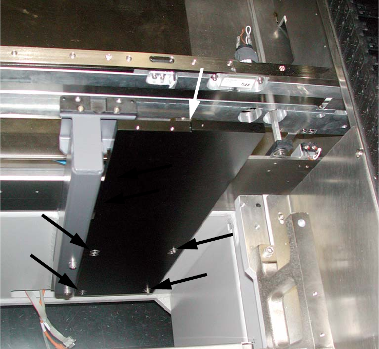
The fiducial plate ("Caul plate for mark") is very heavy! 2
2
2
Assembly instructions Head Reconfiguration SIPLACE D1 / D2
Edition 03/2007
58
: Turn the "Caul for mark" (03039370-), so that the recess is located at the top left (see Fig.
2.7.2).
: Position the "Caul for mark" to coincide with the holes in the machine frame on the set screws.
2
Fig. 2.7.2 "Caul for mark"