00195427-02_AI_HeadReconfigKitsD1D2_DE+EN.pdf - 第89页
Assembly instructions Head Re configuration SIPLACE D 1 / D2 Edition 03/2007 87 2.8.10.1 Fan position for X motor ventilator Both fans of D1 are positioned to cool the X motor of the C&P head at the pick up process. …
Assembly instructions Head Reconfiguration SIPLACE D1 / D2
Edition 03/2007
86
2.8.9 Calibrate all placement heads and cameras
: Calibrate all placement heads, cameras and nozzle changers.
: Perform RV head mapping if necessary.
2
: Back-up the machine data.
2
: Restart again.
This completes the conversion. 2
2
2.8.10 Dismantling of C&P head
By dismantling the C&P head, a SIPLACE D1 becomes a D1 single head (With P&P head). 2
Additional to the conversion work described above (chapter
"Mounting") both placement heads
must be reconfigured in SIPLACE Pro and SITEST. 2
– The C&P head, it’s component camera and nozzle changer must be deleted.
– In SITEST the P&P head with its nozzle changer
must be configured as "Head 1",
that means,
that also the nozzle changer in the SW 603 has to be reconfigured, although it is not changed
mechanically.
– Change thereby the pick up angle in all magazines from 18400 to 400.
Assembly instructions Head Reconfiguration SIPLACE D1 / D2
Edition 03/2007
87
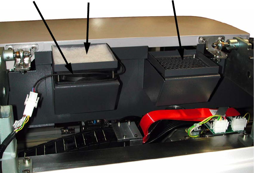
2.8.10.1 Fan position for X motor ventilator
Both fans of D1 are positioned to cool the X motor of the C&P head at the pick up process. 2
Fan
Mount fan to this position
Filter mat
: Dismantle the cover on top of the placement system.
: Mount the fan for the cooling of the X motor to the left position seen from the PCB input side
(4 screws).
2
2
2
2
Assembly instructions Head Reconfiguration SIPLACE D1 / D2
Edition 03/2007
88
2.9 Annex
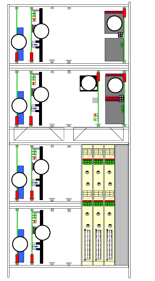
2.9.1 Servocard configuration
A1
A2
A1 A2
CE BE
0IN
ED ON
A3
A4
A3 A4
CE BE
0IN
ED ON
A1
A2
A1 A2
CE BE
0IN
ED ON
A3
A4
A3 A4
CE BE
0IN
ED ON
A1
A2
A1 A2
CE BE
0IN
ED ON
A3
A4
A3 A4
CE BE
0IN
ED ON
1234
TBS 250/10X1
TBS 250 /20Y1
DBM01/01NO2
TBS 250/10X1
TBS 250 /20Y1
DBM01/01NO2
DBM01/01NO2
DBM01/01NO2
LZS250/1000
D4 / D3 Only in Axis unit PA2
A9
A11
A13
A15
A10
A12
A14
A16
15 V / 5A 15 V / 5A5 V / 15A 15V/1,7A 15V/ 1,7A
1
2
3
4
4
5
6
4
6
4
5
Legend
1. DC/DC converter1 5V/15V
2. Ballast circuit
3. DC/DC converter 5V and +/-15V
4. Dynamic brake X/Y
5. Servo amplifier X
6. Servo amplifier Y
A9 bis A16: Head servo positions
2
Fig. 2.9.1 Slots
2