00195427-02_AI_HeadReconfigKitsD1D2_DE+EN.pdf - 第83页
X18 X19 X20 Component camera PCB camera X14 X13 Assembly instructions Head Re configuration SIPLACE D 1 / D2 Edition 03/2007 81 : Connect the following con nectors - 3 x step motors (X18 / X19 / X20) - 2x component camer…
Assembly instructions Head Reconfiguration SIPLACE D1 / D2
Edition 03/2007
80
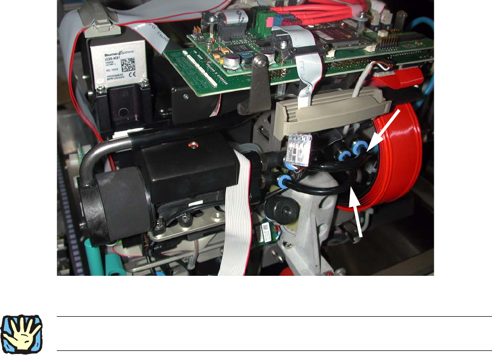
: Fix the silicon hose size 8 and the silicon hose size 6 as shown in Fig. 2.8.4.
2
Fig. 2.8.6 Maintain a distance to the ribbon cable
2
2
2
2
2
2
2
2
2
2
2
2
2Cable routing must take place as described in the service instructions D1/D2, FS 03, chapter on
cable routing! 2
X18
X19
X20
Component
camera
PCB
camera
X14
X13
Assembly instructions Head Reconfiguration SIPLACE D1 / D2
Edition 03/2007
81
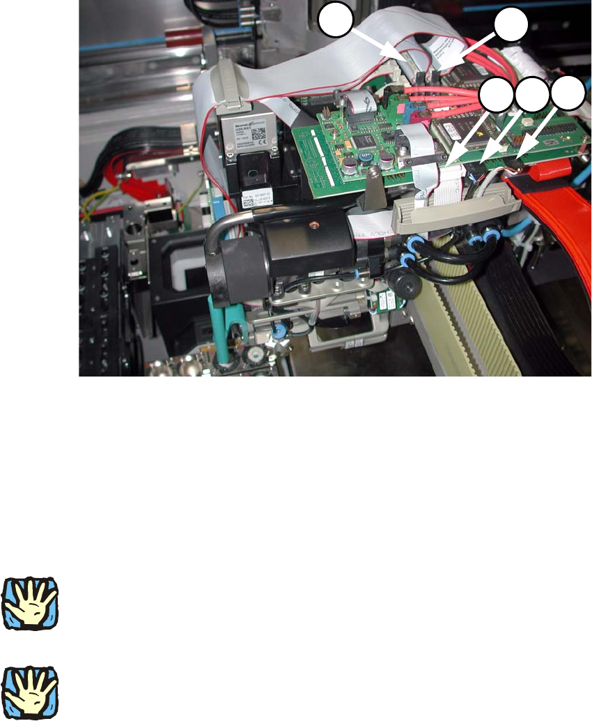
: Connect the following connectors
- 3 x step motors (X18 / X19 / X20)
- 2x component camera
(2x PCB camera are already connected).
2
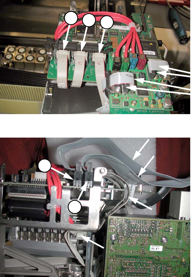
Fig. 2.8.7 5 cables: left (00359364-), centre (00367074-), right (00350382-) and 2x component camera
2
Fig. 2.8.8 2 ribbon cables of the placement head ( Fig. 2.8.7 viewed from the left)
X22
X12X10
X13
X14
Assembly instructions Head Reconfiguration SIPLACE D1 / D2
Edition 03/2007
82
2
Fig. 2.8.9 Plug in two cables
2
: Fix the 4 cables with the strain relief.
2
2.8.6 Replacing the servo cards
2
Wear an ESD armband for the whole time you are working on the placement head and servos! 2
2
: Use the machine key to open the door of the servo unit.
2
Place the axis and servo cards in accordance with your machine configuration.
See the diagram in the annex (Chapter 2.9.1). 2
2
2
2
2