00198460-01_DC_SIPLACE_TX-EditionV2_DE+EN.pdf - 第9页
electric_schematic SIPLACE TX_V2 electric_schematic SIPLACE TX_V2 electric_schematic SIPLACE TX_V2 electric_schematic SIPLACE TX_V2 90012669-010501LE3 Replaced by P ower- Supplies, MGCU, Fuse & Distribution P ower- S…
electric_schematic SIPLACE TX_V2
electric_schematic SIPLACE TX_V2
electric_schematic SIPLACE TX_V2
electric_schematic SIPLACE TX_V2
90012669-010501LE3
Replaced by
Graphics top-view
Graphics top-view
Graphics top-view
Graphics top-view
inside-modules
inside-modules
inside-modules
inside-modules
Replaced by
Weitergabe sowie Vervielfältigung dieser Unterlage, Verwertung und
Mitteilung des Inhalts nicht gestattet, soweit nicht ausdrücklich zugestanden.
Proprietary Data, company confidential.
All rights reserved
Copying of this document, giving it to others and the use or
communication of the contents thereof, are forbidden without express authority.
Doc. No.
Privileged business information.
Do not release
Offenders are liable to payment of damages. All rights are reserved in the
event of the grant or the registration of a utility model or design.
Zuwiederhandlungen verpflichten zu Schadenersatz. Alle Rechte vorbehalten,
insbesondere für den Fall der Patenterteilung oder GM-Eintragung vorbehalten.
Page:
Function: Overview Graphics
==OVGR=TX/3
drawing number:
03110650-010201LE3
overview_graphics
o
verview_graphics
overview_graphics
overview_graphics
GmbH & Co KG
ASM
Assembly Systems
Copyright reserved
Ed.
Original
Pingist
Date
Date
Modification
Appr
08.03.2018
Name
Size DIN A2
Sheet
3
/
1
Location 1
Location 1
Location 1
Location 1Location 2
Location 2
Location 2
Location 2
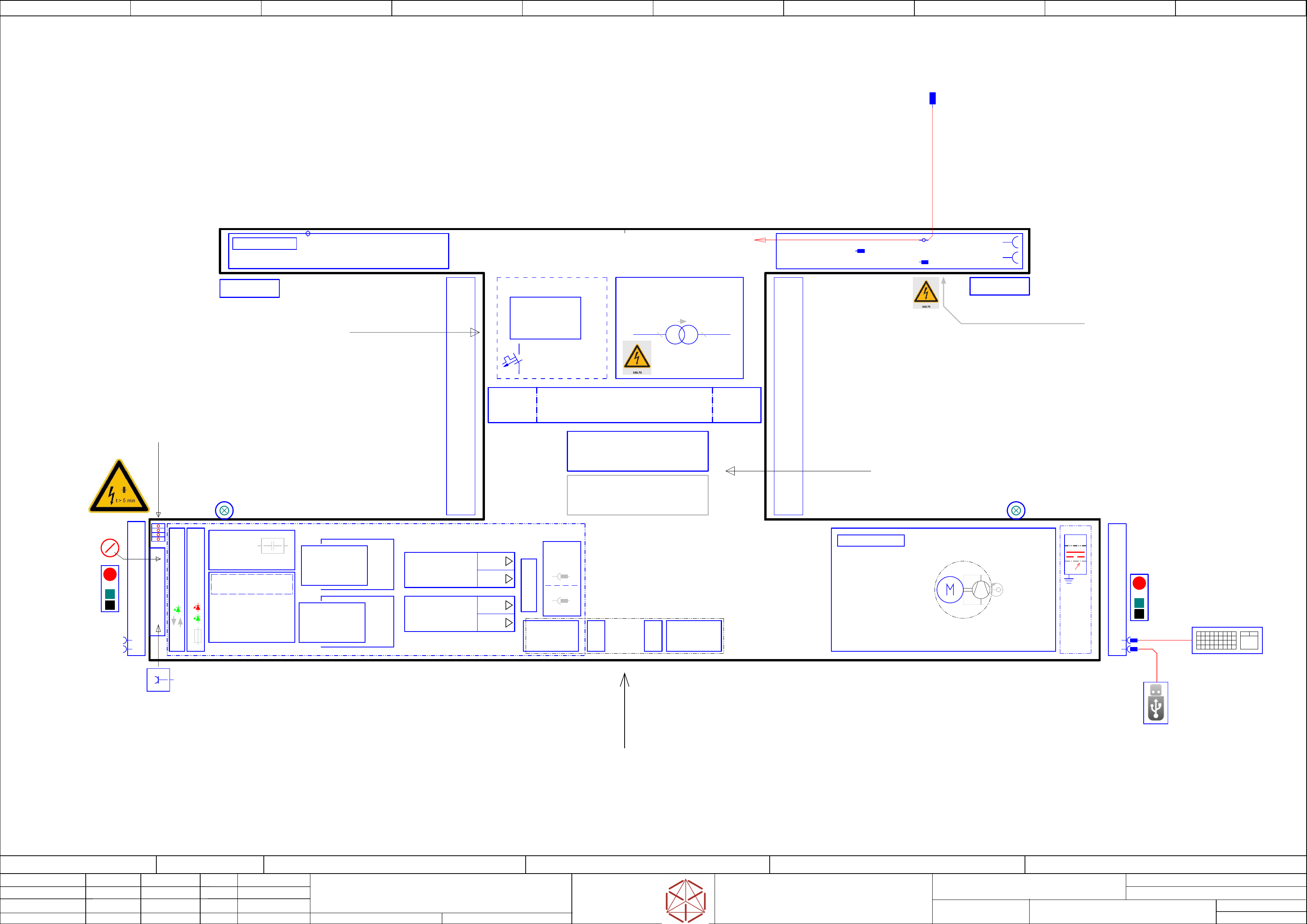
Main switch
Start
Emergency Stop
Stop
Start
Stop
Emergency Stop
PCB Transfer
Interface Extern Connections
Interface Extern Connections
Interface Extern Connections
Interface Extern Connections
-DIC
-FDC
Connector-
Field
3Ph/Mot4
3Ph/Mot3
3Ph/Mot2
3Ph/Mot1
USB keyboard with touch pad
(only for service)
==CH+CTRL/60.03
PSU1 & MGCU unit
PSU1 & MGCU unit
PSU1 & MGCU unit
PSU1 & MGCU unit
- above -
Sercice_access
FCUS & Transformer
Connection
-Feld 2
Connection
-Feld 1
Sercice_access PC´s
3
~
3
~
Service Testing-Point
DC 300/160 V IN/OUT
==ME+03146155/43.04
==FLUID-VACP
Vacuum_Pump
- Optional -
==FLUID-U1
==FLUID-U1
==FLUID-U1
==FLUID-U1
==FLUID/111.00
Pneumatic-group P001
Main_Pneumatics_connection
Main_valves
4x SMEMA-Interface
==CO008+L1/98.05
LAN2 extern_Connection
RJ45
==CH+CTRL/60.05
-X1
-
X1
-X1
-X1
Mains Connection
Mains Connection
Mains Connection
Mains Connection
CEE-connector
5-pole 6h 16A/400V
Service Socket
230VAC(110VAC)
1/N/PE
CAN Interface CIN
==CH+CTRL/60.00
-MGCU2
-MGCU2
-MGCU2
-MGCU2
Position controller MGCU
Gantry 2 axis X/Y
==CH+GA/63.00
-MGCU1
-MGCU1
-MGCU1
-MGCU1
Position controller MGCU
Gantry 1 axis X/Y
==CH+GA/61.00
Fuse- and Distribution PCB
==ME+03146155/45.00
CAN- I/O control unit III
==ME+03147585/47.00
Service_Panel
Monitor-2
Monitor-2
Monitor-2
Monitor-2
==CH+CTRL/60.05
USB A plug
USB-STICK 3.0(2.0)
Service (Data-handling)
==CH+CTRL/60.05
Control-elements-1
Control-elements-2
USB
Monitor-1
Monitor-1
Monitor-1
Monitor-1
==CH+CTRL/60.01
USB
Service
Fault indicator lamp 2
Fault indicator lamp 1
Hood switch S2
==CH+03148020/56.00
-A2
Safety breaker
PCB Pre-/discharge assembly
-PS1
-PS1
-PS1
-PS1
DC 24V PELV
==ME+03146155/45.03
-PS3
-PS3
-PS3
-PS3
DC 42V / FELV
==ME+03146155/45.01
-PS4
-PS4
-PS4
-PS4
Power-supply 3AC
380-400V 1,2KW
==ME+03146155/43.01
-TI1
-TI1
-TI1
-TI1
Trailing interface 1
==CH+GA/61.00
-TI2
-
TI2
-TI2
-TI2
Trailing interface 2
==CH+GA/63.00
-VBI1
-VBI1
-VBI1
-VBI1
Vision
Base-Interface 1
==CH+GA/62.05
-VBI2
-VBI2
-VBI2
-VBI2
Vision
Base-Interface 2
==CH+GA/64.05
-X2
-
X2
-X2
-X2
2x Shuttle-Interface
==CH+03147980/54.01
CAN3.EXT
-T1
-
T1
-T1
-T1
3P208V/400V/5,05A
==ME+03155560/39.00
3Ph 400V
Transformer
T
ransformer
Transformer
Transformer
US voltage adaption kit (Option)
US v
oltage adaption kit (Option)
US voltage adaption kit (Option)
US voltage adaption kit (Option)
==ME+03155560/39.00
3Ph 200V
-Slim_FCU
-Slim_FCU
-Slim_FCU
-Slim_FCU
Slim-FCU Location-1
Sl
im-FCU Location-1
Slim-FCU Location-1
Slim-FCU Location-1
==03146501+Loc1/68.00
-Slim_FCU
-Slim_FCU
-Slim_FCU
-Slim_FCU
Slim-FCU Location-2
Sl
im-FCU Location-2
Slim-FCU Location-2
Slim-FCU Location-2
==03136891+Loc2/73.00
-FCUS-PS6
-FCUS-PS6
-FCUS-PS6
-FCUS-PS6
DC Out 27V/40A PELF
Control-Power FCU
-FCUS
-FCUS
-FCUS
-FCUS
-PC
-PC
-PC
-PC
Control computer
Contr
ol computer
Control computer
Control computer
BoxPC-427D i3 2xPCIe
B
oxPC-427D i3 2xPCIe
BoxPC-427D i3 2xPCIe
BoxPC-427D i3 2xPCIe
==CH+CTRL/60.02
-PC2
-PC2
-PC2
-PC2
Control computer
BoxPC-427D i7 2xPCIe
Option for Bulk_Feeder
Vacuum_Panel_V20
Vacuum_Panel_V20
Vacuum_Panel_V20
Vacuum_Panel_V20
Frequency_Converter
Fr
equency_Converter
Frequency_Converter
Frequency_Converter
==ME+03151645/51.00
Option
-T1
-
T1
-T1
-T1
SINAMICS V20
SINAMICS V20
SINAMICS V20
SINAMICS V20
3AC 380-480V
1,1 kW (without Filter)
==ME+03151645/51.03
-FCU.CA
-FCU
.CA
-FCU.CA
-FCU.CA
PCBA_FCU Connection Assembly TX_V2
==03146501+FCU_CA/66.00
-M1
-M1
-M1
-M1
Vacuumpump
V
acuumpump
Vacuumpump
Vacuumpump
Becker VX4.25
(0,75KW, 25m³/h)
Hood switch S2
==CH+03148020/56.03
-CAP1
-CAP1
-CAP1
-CAP1
DC 300/150
Capacitor Bank
==ME+03146155/43.01
-PS2
-PS2
-PS2
-PS2
DC 42V / PELV
==ME+03146155/45.02
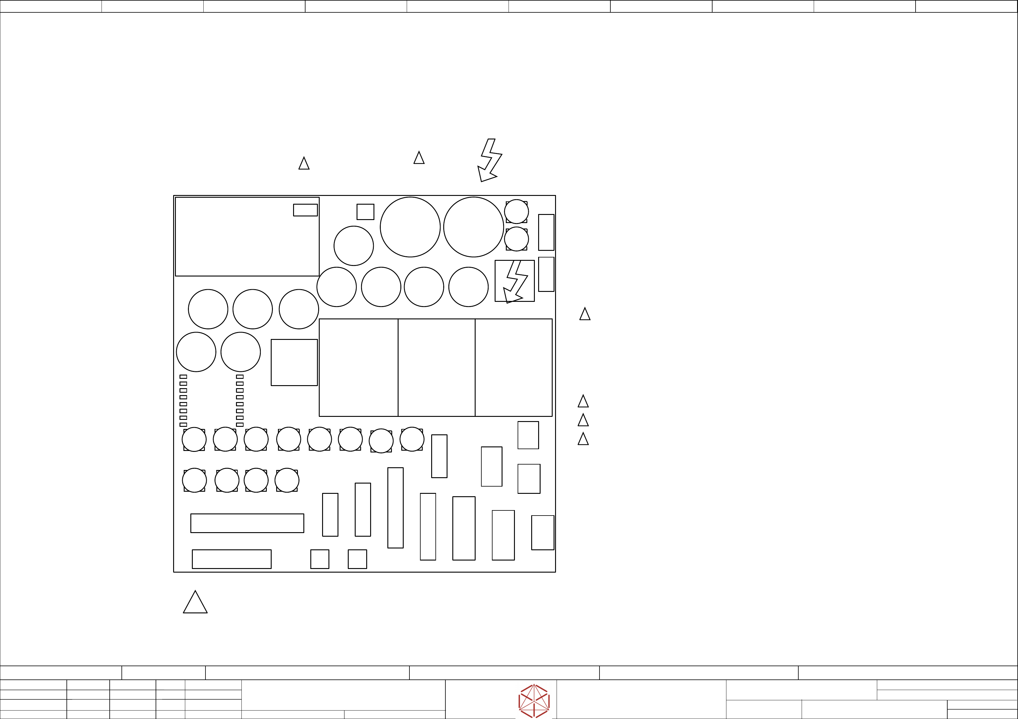
F1 - F21
-CSB
-CSB
-CSB
-CSB
DC 300/150
Capacitor Bank
==ME+03146155/44.00
-F31
-F32
-F33
1
G1/2
G1/2
G1/2
G1/2
Main-connection air-pressure
Main-connection air
-pressure
Main-connection air-pressure
Main-connection air-pressure
p= 5 to 10bar
by 500NL/min
03065265-
==FLUID/111.00
access to Extern connection
24x OUT
40x IN
electric_schematic SIPLACE TX_V2
electric_schematic SIPLACE TX_V2
electric_schematic SIPLACE TX_V2
electric_schematic SIPLACE TX_V2
90012669-010501LE3
Replaced by
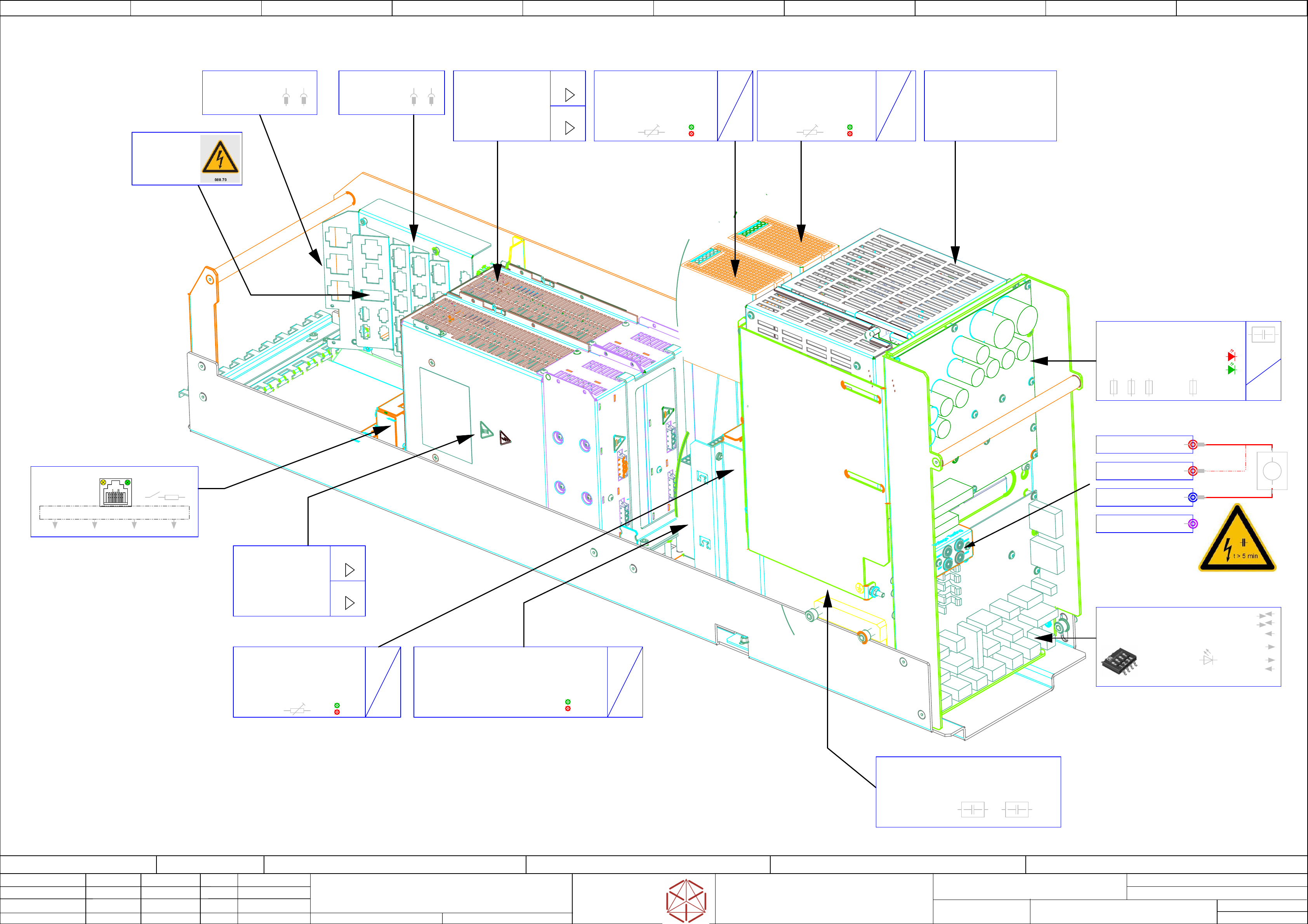
Power-Supplies, MGCU, Fuse & Distribution
Power-Supplies, MGCU, Fuse & Distribution
Power-Supplies, MGCU, Fuse & Distribution
Power-Supplies, MGCU, Fuse & Distribution
Overview
Ov
erview
Overview
Overview
Replaced by
Weitergabe sowie Vervielfältigung dieser Unterlage, Verwertung und
Mitteilung des Inhalts nicht gestattet, soweit nicht ausdrücklich zugestanden.
Proprietary Data, company confidential.
All rights reserved
Copying of this document, giving it to others and the use or
communication of the contents thereof, are forbidden without express authority.
Doc. No.
Privileged business information.
Do not release
Offenders are liable to payment of damages. All rights are reserved in the
event of the grant or the registration of a utility model or design.
Zuwiederhandlungen verpflichten zu Schadenersatz. Alle Rechte vorbehalten,
insbesondere für den Fall der Patenterteilung oder GM-Eintragung vorbehalten.
Page:
Function: Overview Graphics
==OVGR=TX+ME/4
drawing number:
03133452-010501LE3
overview_graphics
o
verview_graphics
overview_graphics
overview_graphics
GmbH & Co KG
ASM
Assembly Systems
Copyright reserved
Ed.
Original
Pingist
Date
Date
Modification
Appr
07.02.2018
Name
Size DIN A2
Sheet
4
/
5
3Ph/Mot3
3Ph/Mot4
3~
3~
3~
3~
=
=
=
=
Overload
DC ok
Adjust
36-42V
-PS3
-PS3
-PS3
-PS3
AC/DC converter DC36V/13.3A 3P
AC/DC con
verter DC36V/13.3A 3P
AC/DC converter DC36V/13.3A 3P
AC/DC converter DC36V/13.3A 3P
PULS.QT20.361
03076588
DC 42V / FELV
DC 42V / FEL
V
DC 42V / FELV
DC 42V / FELV
==ME+03146155/45.01
CAN1 CAN2 CAN3 CAN4
LAN
CAN-termination
(120 Ohm = off)
LAN to CAN_converter
DC 25V Puff1
DC 42V
DC 25V Puff2
discharge-
Head-buffer
RED: individual voltage
monitoring (on Board)
GREEN: Diagnostic OK
. . . . .
. . . . .
. . . . .
. . . . .
3Ph/Mot1
3Ph/Mot2
3~
3~
3~
3~
=
=
=
=
Vout1>220V
Vout1<220V
-PS4
-PS4
-PS4
-PS4
Converter AC3~ 380-415 V/DC300 and 160 V; 1,2kW
Con
verter AC3~ 380-415 V/DC300 and 160 V; 1,2kW
Converter AC3~ 380-415 V/DC300 and 160 V; 1,2kW
Converter AC3~ 380-415 V/DC300 and 160 V; 1,2kW
PULS.QT40-999-70
03103087
Motion DC-Out1 300V / DC-Out2 160V
Motion DC
-Out1 300V / DC-Out2 160V
Motion DC-Out1 300V / DC-Out2 160V
Motion DC-Out1 300V / DC-Out2 160V
==ME+03146155/43.01
3~
3~
3~
3~
=
=
=
=
Overload
DC ok
Adjust
3~
3~
3~
3~
=
=
=
=
Overload
DC ok
Adjust
24-28V
-PS1
-PS1
-PS1
-PS1
AC/DC converter DC24V/20A 3P
AC/DC con
verter DC24V/20A 3P
AC/DC converter DC24V/20A 3P
AC/DC converter DC24V/20A 3P
PULS.QT20.241
03055232
==ME+03146155/45.03
Dip-Switch S1
CAN-Bus termination = on
DC 300 V DC 160 V
-CAP1
-CAP1
-CAP1
-CAP1
Capacitor unit 38 mF including diagnostic master
Capaci
tor unit 38 mF including diagnostic master
Capacitor unit 38 mF including diagnostic master
Capacitor unit 38 mF including diagnostic master
PULS.PCS417.381
03103081
==ME+03146155/43.01
-F1
-F2
-F4
-F23
-DI
-DI
-DI
-DI
CAN- I/O control unit III
CAN- I/O contr
ol unit III
CAN- I/O control unit III
CAN- I/O control unit III
03147585
==ME+03147585/47.00
-MGCU2
-MGCU2
-MGCU2
-MGCU2
Position controller MGCU-2
Gantry 2 axis X/Y
03117531
==CH+GA/63.00
-X303
-
X303
-X303
-X303
DC 300 V OUT
==ME+03146155/43.03
-X304
-
X304
-X304
-X304
DC 300V
==ME+03146155/43.04
-X305
-
X305
-X305
-X305
GND
==ME+03146155/43.04
DC link voltage testing panel
Safety-instructions
Safety-instructions
Safety-instructions
Safety-instructions
see Service-Documentation
see Service-Documentation
see Service-Documentation
see Service-Documentation
V
-?CIN1
-?CIN1
-?CIN1
-?CIN1
CAN Interface CIN
03108598
-FD.A1
-FD
.A1
-FD.A1
-FD.A1
Fuse- and Distribution PCB TX_V2
Fuse- and Distribution PCB TX_V2
Fuse- and Distribution PCB TX_V2
Fuse- and Distribution PCB TX_V2
03136970
==ME+03146155/45.00
-MGCU1
-MGCU1
-MGCU1
-MGCU1
Position controller MGCU-2
Gantry 1 axis X/Y
03117531
==CH+GA/61.00
-PS2
-PS2
-PS2
-PS2
AC/DC converter DC36V/13.3A 3P
AC/DC con
verter DC36V/13.3A 3P
AC/DC converter DC36V/13.3A 3P
AC/DC converter DC36V/13.3A 3P
PULS.QT20.361
03076588
DC 42V / PELV
DC 42V / PEL
V
DC 42V / PELV
DC 42V / PELV
==ME+03146155/45.02
-CSB
-CSB
-CSB
-CSB
Safety Breaker V2
Unit Safety Breaker (CSB) V2
Uni
t Safety Breaker (CSB) V2
Unit Safety Breaker (CSB) V2
Unit Safety Breaker (CSB) V2
000.03160454
03112066
Contactor based safety breaker
Contactor based saf
ety breaker
Contactor based safety breaker
Contactor based safety breaker
==ME+03146155/44.00
-X1.PLS
-
X1.PLS
-X1.PLS
-X1.PLS
Mains input PLS
3x 400V AC
==ME+03146155/43.00
-DIC
-DIC
-DIC
-DIC
Connector panel
Distributor TX_V2
==CH+03148020/55.00
-FDC
-FDC
-FDC
-FDC
Power connector panel
Fuse & Distribution
==CH+03147980/52.00
-X306
-
X306
-X306
-X306
DC 160 V OUT
==ME+03146155/44.03
24x OUT(24V)
40x IN(24V)
2x RS485
CAN1
CAN2
CAN3(Service)
electric_schematic SIPLACE TX_V2
electric_schematic SIPLACE TX_V2
electric_schematic SIPLACE TX_V2
electric_schematic SIPLACE TX_V2
90012669-010501LE3
Replaced by
Machine label Power unit F&D
Machine label Power unit F&D
Machine label Power unit F&D
Machine label Power unit F&D
Replaced by
Weitergabe sowie Vervielfältigung dieser Unterlage, Verwertung und
Mitteilung des Inhalts nicht gestattet, soweit nicht ausdrücklich zugestanden.
Proprietary Data, company confidential.
All rights reserved
Copying of this document, giving it to others and the use or
communication of the contents thereof, are forbidden without express authority.
Doc. No.
Privileged business information.
Do not release
Offenders are liable to payment of damages. All rights are reserved in the
event of the grant or the registration of a utility model or design.
Zuwiederhandlungen verpflichten zu Schadenersatz. Alle Rechte vorbehalten,
insbesondere für den Fall der Patenterteilung oder GM-Eintragung vorbehalten.
Page:
Function: Overview Graphics
==OVGR=TX+ME/5
drawing number:
03146155-010701LE3
overview_graphics
o
verview_graphics
overview_graphics
overview_graphics
GmbH & Co KG
ASM
Assembly Systems
Copyright reserved
Ed.
Original
Pingist
Date
Date
Modification
Appr
24.01.2018
Name
Size DIN A2
Sheet
5
/
5
F1
F1
F1
F1 F12
F12
F12
F12 F21
F21
F21
F21 F11
F11
F11
F11 F16
F16
F16
F16 F15
F15
F15
F15 F14
F14
F14
F14 F6
F6
F6
F6
F3
F3
F3
F3 F4
F4
F4
F4 F5
F5
F5
F5 F7
F7
F7
F7
X25
X25
X25
X25
X26
X26
X26
X26
X5
X5
X5
X5
X1
X1
X1
X1
X16
X16
X16
X16
X9
X9
X9
X9
X10
X10
X10
X10
X14
X14
X14
X14
X15
X15
X15
X15
X13
X13
X13
X13
X8
X8
X8
X8
X17
X17
X17
X17
X24B
X24B
X24B
X24B
X12
X12
X12
X12 X11
X11
X11
X11
XB8B
XB8B
XB8B
XB8B XB8A
XB8A
XB8A
XB8A
F19
F19
F19
F19
F20
F20
F20
F20
DC/DC1
DC/DC1
DC/DC1
DC/DC1
(BUFF1)
(BUFF1)
(BUFF1)
(BUFF1)
C109
C109
C109
C109C110
C110
C110
C110
C107
C107
C107
C107
C106
C106
C106
C106
C105
C105
C105
C105
C104
C104
C104
C104 C103
C103
C103
C103 C102
C102
C102
C102 C101
C101
C101
C101
C108
C108
C108
C108
C2
C2
C2
C2
C26
C26
C26
C26
Diagnostic unit
Diagnostic unit
Diagnostic unit
Diagnostic unit
X2
X2
X2
X2
DC/DC2
DC/DC2
DC/DC2
DC/DC2
(BUFF2)
(BUFF2)
(BUFF2)
(BUFF2)
DC/DC3
DC/DC3
DC/DC3
DC/DC3
(MGCU)
(MGCU)
(MGCU)
(MGCU)
X24A
X24A
X24A
X24A
F1
F3
F4
F5
F6
F7
F10
F11
F12
F13
F14
F15
F16
F19
F20
F21
42V
24V
24V
24V
42V
24V
24V
24V
24V
24V
42/24V
42/24V
42V
160V
160V
42V
6,3 A T
6,3 A T
4 A T
6,3 A T
6,3 A T
6,3 A T
POLYFUSE
6,3 A T
6,3 A T
3 A SMD
6,3 A T
6,3 A T
10 A T
6,3 A T
6,3 A T
6,3 A T
Shuttle 42V
Shuttle 24V & Option
Distributor
Monitor 1&2 / CIN
MGCU supply 42 V
Conveyor control
Internal
CSB Signal
CSB supply 24V-S
Diagnostic supply
Gantry/Head 1
Gantry/Head 2
Conveyor drives
Gantry 1
Gantry 2
(Vision) not used
F31
F32
F33
27,5V
27,5V
27,5V
16 A C
16 A C
10 A C
FCU 1 (27V_FCU1)
FCU 2 (27V_FCU2)
Station PC (27V_PC)
Risk of fire and electric shock!
Risk of fire and electric shock!
Risk of fire and electric shock!
Risk of fire and electric shock!
Replace fuses by specified service parts only!
Replace fuses by specified service parts only!
Replace fuses by specified service parts only!
Replace fuses by specified service parts only!
!
safety
safety
safety
safety
controlled
controlled
controlled
controlled
voltage
voltage
voltage
voltage
S
S
S
S
Indicator near fuse will show that
Indicator near fuse will show that
Indicator near fuse will show that
Indicator near fuse will show that
fuse is blown or
fuse is blown or
fuse is blown or
fuse is blown or
safety controlled voltage
safety controlled voltage
safety controlled voltage
safety controlled voltage
is off
is off
is off
is off
High Voltage
High Voltage
High Voltage
High Voltage
behind cover
behind cover
behind cover
behind cover
S
S
S
S
S
S
S
S
S
S
S
S
S
S
S
S
Line Breakers (at FCU supply unit)
Line Breakers (at FCU supply unit)
Line Breakers (at FCU supply unit)
Line Breakers (at FCU supply unit)
Status
Status
Status
Status
POWER ENABLE
POWER ENABLE
POWER ENABLE
POWER ENABLE
POWER OK
POWER OK
POWER OK
POWER OK
K1 OK
K1 OK
K1 OK
K1 OK
K2 OK
K2 OK
K2 OK
K2 OK
POWER FAIL
POWER F
AIL
POWER FAIL
POWER FAIL
POWER FAIL PS2
POWER F
AIL PS2
POWER FAIL PS2
POWER FAIL PS2
27V PC
27V PC
27V PC
27V PC
+3V3
+3V3
+3V3
+3V3
+5V0 EXT
+5V0 EXT
+5V0 EXT
+5V0 EXT
DC 24V_S_CO
DC 24V_S_CO
DC 24V_S_CO
DC 24V_S_CO
P24V_MGCU
P24V_MGCU
P24V_MGCU
P24V_MGCU
P24V_BUFF1
P24V_BUFF1
P24V_BUFF1
P24V_BUFF1
P24V_BUFF2
P24V_BUFF2
P24V_BUFF2
P24V_BUFF2
27V_FCU1
27V_FCU1
27V_FCU1
27V_FCU1
27V_FCU2
27V_FCU2
27V_FCU2
27V_FCU2
V2
V2
V2
V2
PE
PE
PE
PEGND
GND
GND
GND
S
S
S
S
03152559-030101GX4