196396 Iss 2 Nov 2015 - Semi Appendix Manual.pdf - 第43页
POWER SUPPLY AND DISTRIBUTION OVERVIEW 6.2 Technical Reference Manual Chapter Issue 3, Nov 14 WARNING LETHAL VOLTAGE. DANGEROUS VOLT AGES EXIST IN THIS EQUIPMENT. ENSURE ALL ELECTRONIC COVERS AN D MAIN MACHINE C OVERS AR…
POWER SUPPLY AND DISTRIBUTION
OVERVIEW
Chapter Issue 3, Nov 14 Technical Reference Manual 6.1
CHAPTER 6 POWER SUPPLY AND DISTRIBUTION
OVERVIEW
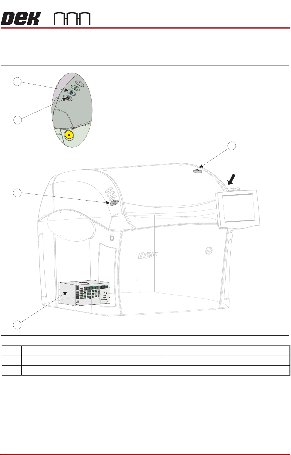
Item Description Item Description
1 Front Cover Interlock 3 Two Button Control
2 M37 Power Supply Enclosure 4 System Button
A
View on Arrow A
3
4
3
1
2

POWER SUPPLY AND DISTRIBUTION
OVERVIEW
6.2 Technical Reference Manual Chapter Issue 3, Nov 14
WARNING
LETHAL VOLTAGE. DANGEROUS VOLTAGES EXIST IN THIS EQUIPMENT.
ENSURE ALL ELECTRONIC COVERS AND MAIN MACHINE COVERS ARE FITTED
BEFORE OPERATING THIS EQUIPMENT.
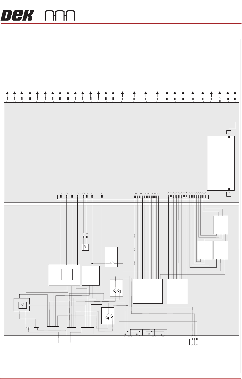
Mains input power (115V to 230V) to the machine is routed via the mains isolator
switch and the M39 EMO enclosure. From the M39 enclosure it is fed to the M37
power supply crate, through the cable gland at the rear panel, to the three
terminal blocks TB1 (live), TB2 (neutral) and TB3 (earth). From the terminal
blocks mains power is supplied to the following:
• M37SK31 PC Supply
• M37SK32 Monitor Supply
• M37SK33 Spare
• M37SK34 Spare
• M37SK35 Internal Vac Pump via Mains Filter and CB34
• PSU 1
• PSU 2
PSU 1 is a 350W high range input Switched Mode Power Supply Unit (SMPSU)
which converts the ac into the following dc supplies:
•+24V US
• +24V SW
•+5.5V
•+12V
•-12V
PSU 2 is a 600W high range input Switched Mode Power Supply Unit (SMPSU)
which converts the ac into dc. The PSU 2 supplies +48V dc.
The dc supplies from both PSU 1 and PSU 2 are fed to the power distribution
PCB. Mounted on the power distribution PCB is the PSU monitor board which
enables monitoring of the power supplies.
A printhead cover loop consisting front cover interlock, interlock blanking plug
and E Stop relay are fitted to ensure motor power is removed if the front
printhead cover is opened.
A two handed safety relay, left jog button and right jog button are fitted to enable
certain functions to be performed with the front printhead cover open.
NOTE
Following a service visit that involves any disturbance of components in the
mains voltage circuit an electrical test as detailed in the Pre Power section of
the Transportation chapter must be undertaken. Before testing ensure that the
machine is isolated from the factory supply and that any external equipment (ie
upline and downline conveyors) are disconnected.
POWER SUPPLY AND DISTRIBUTION
ELECTRICAL SCHEMATIC
Chapter Issue 3, Nov 14 Technical Reference Manual 6.3
ELECTRICAL SCHEMATIC
M37 Power
Supply Crate
CB 32
10A
CB 3 10A
CB 4 10A
PSU 1
L
N
E
L
N
E
+24V
-12V
+12V
+5.5V
PSU 2
+48V
Filter
TB2
TB3
TB1
L
N
E
TB4
TB5
M37SK31
PC Supply
M37SK32
Monitor
Supply
M37SK33
Spare
M37SK34
Spare
M37SK35
Internal V
ac Supply
2 Handed
Safety Relay
PIHZ X1
RL2
E Stop Relay
PNOZ X2
RL1
M37TB01
Power
Distribution PCB
M37SK36
Part
CON1
Part
CON2
Part
CON3
50
51
CON1
CON3
CON2
Fan
MMI
M37SK27
Safety I/O
M37PL26
M37SK24
E Stop Blanking
Plug
M37SK30
To PC
USB Port
M37SK23
Rear Cover Interlock/
Interlock Blanking
Plug
M37SK22
Front Cover Interlock
M37SK21
Spare Servo Motor Power
M37SK20
RTC I/O Node 1
1
M37SK19
Camera Y I/O Node 9
Servo Motor Power
M37SK18
Camera X I/O Node 8
Servo Motor Power
+5.0V
M37SK01
Rising Table I/O Node 6
Servo Motor Power
M37SK16
M37SK17
Print Carriage
I/O Node 7
Servo Motor Power
NextMove
DC
M37SK02
Motor DC
M37SK03
Machine
I/O Node 2
M37SK04
Print Carriage
I/O Node 3
M37SK05
USC I/O Node 4
M37SK06
OTS/HTC I/O Node 5
M37SK07
Paste Dispense
I/O Node 10
M37SK08
HTC M27/RTC I/O Node 12
M37SK09
FormF
lex/Grid-
Lok ProActiv
M37SK10
Internal Lighting
& Ionizer
M37SK11
LED Stencil Backlight Panel
M37SK12
Remote
Barcode
Reader
M37SK13
Hand Held Barcode
Reader
M37SK14
Machine
Fans
M37SK15
PSU Monitor
Board
M37PL28
M37PL29
M37SK25
From 2-Pole
25A Isolator
and M39
EMO
Enclosure
E Stop Blanking
Plug