196396 Iss 2 Nov 2015 - Semi Appendix Manual.pdf - 第71页
PREVENTIVE MAINTENANCE DESCRIPTION OF THE MONTHLY MAINTENANCE SCHEDULE 28.10 Technical Reference Manual Chapter Issue 5, Aug 14 DESCRIPTION OF THE MONTHL Y MAINTENANC E SCHEDULE Introduction T wo modules form the basis o…
PREVENTIVE MAINTENANCE
DAILY MAINTENANCE
Chapter Issue 5, Aug 14 Technical Reference Manual 28.9
NOTE
Any items heavily contaminated requiring thorough cleaning must be re-lubri-
cated in accordance with the appropriate monthly maintenance task, where
appropriate.
12 HTC Flat Belt Option:
a. Remove debris.
b. Check for any wear of belt coating or
damage.
c. If contaminated with flux, replace
belts.
Spatula
13 TRS Option:
a) Remove debris
b) Clean surfaces; Rail Cap; Active
Surround; Tooling Caps; TRP; Vacuum
Chamber and area beneath the rails;
Contact points under the TRP.
DO NOT IMMERSE TOOLING
Spatula
Lint Free Cloth
De-ionized
water
Estimated time required for daily tasks 15.0 mins
SEMI Level No Task Tools Completed Reference Figure
SEMI1
SEMI1
Summary/Remarks
Signed: Date:

PREVENTIVE MAINTENANCE
DESCRIPTION OF THE MONTHLY MAINTENANCE SCHEDULE
28.10 Technical Reference Manual Chapter Issue 5, Aug 14
DESCRIPTION OF THE MONTHLY MAINTENANCE SCHEDULE
Introduction Two modules form the basis of the monthly schedule. The process requires that
each month a machine repeatability check is performed on Squeegee Pressure
and the X, Y and Theta axes. This is done using the Statistical Process Control
(SPC) data collection program (where available).
Module 1 The first module comprises the following elements:
• SPC Alignment Check - used to set a benchmark each month, the hard-
ware is checked to give a snapshot of the machine condition, performance
is monitored to predict failure before it has an affect on production.
• Machine Cycle Count - machine usage is logged in the table.
• A Software Check is carried out, if a newer version is available this may
contain known defect fixes or equipment enhancements. The service
engineer can recommend an upgrade for the equipment in service. In
addition, the machine event log is checked to identify any re-occurring
errors which if not inspected/diagnosed may lead to unplanned downtime.
• A standard Monthly Maintenance Check consists of a series of mainte-
nance tasks which are performed every month.
Machine safety checks are carried out on a basis as laid down in the monthly
schedule. In addition, the engineer performs maintenance on set machine
modules, checks software version and records the cycle count.
Module 2 In this module, over the course of a year, the following assemblies are checked.
• Printhead
• All Electrical Enclosures
• Camera System
• Squeegee Mechanism
• Rising Table
• Paste Dispenser
• ProFlow
• Temperature Control Module (TCM)
• Screen Alignment
• DC Supplies
• Vacuum Filtration Unit
• Pneumatic System
• Safety System
• Rail System
• Print Carriage
• Machine Level
• Screen Change
• Adjustable Screen Mount (ASM)
• Topside Referencing System (TRS) Option
PREVENTIVE MAINTENANCE
DESCRIPTION OF THE MONTHLY MAINTENANCE SCHEDULE
Chapter Issue 5, Aug 14 Technical Reference Manual 28.11
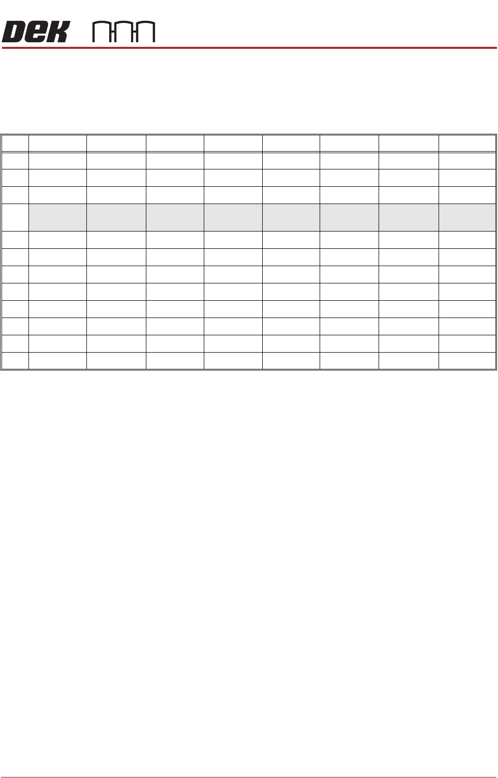
Accuracy Check For an accuracy check, except where stated otherwise, thirty test cycle meas-
urements are set (preceded by ten cycles unmeasured to allow the machine to
settle). Pre and Post print measurements are taken to record the accuracy of
the alignment in CPK values and the front and rear squeegee pressures
displayed in bar units.
SPC Results Where the QC Calc for Windows program is installed and customers have
employed the ASM Equipment Utilization Programme, SPC data capture can
graphically show critical alignment and squeegee pressure accuracy. The
graphs in their visual form are often useful in determining the optimum mainte-
nance plan.
NOTE
ASM Equipment Utilization Programme is available from ASM Customer Sup-
port Group.
Customers may opt to use the collected data in their own management system,
ASM cannot provide support for any programme other than ASM EUP.
Examining the
Collected Data
In addition to examining the SPC data which is displayed graphically in the QC
Calc for Windows program, engineers can extract information about machine
performance from other sources.
The data collected on the machine is stored in ‘event.dat’ and ‘readings.dek’
files, accessible in the following locations, E:\config\readings.dek for SPC
data and E:\config\event.dat for error occurrences. Information can be dis-
played in a text editor and specific data can be examined eg, events between
Visit Pre X Pre Y Pre Theta Post X Post Y Post Theta Front Sqy Rear Sqy
1st 2.00 1.63 1.97 1.84 1.40 1.60 5.15 4.86
2nd 1.89 1.63 1.84 1.80 1.40 1.60 5.00 4.86
3rd 1.86 2.00 1.98 1.48 1.48 1.70 4.98 4.86
4th
100 Cycles
1.84
100 Cycles
1.94
100 Cycles
1.76
100 Cycles
1.63
100 Cycles
1.46
100 Cycles
1.56
100 Cycles
4.50
100 Cycles
4.80
5th
6th
7th
8th
9th
10th
11th
12th