Formflex Manual.pdf - 第14页
TECHNI CAL R EFEREN CE ADJUS TMEN TS AND SE TTINGS Chapter Issue 4 Jun 04 FormFlex Tooling M anual 1.7 6. If th e setting weight has been lif ted from t he manual tooling plate, pr ess the green reset but ton located ins…
1.6 FormFlex Tooling Manual Chapter Issue 4 Jun 04
TECHNICAL REFERENCE
ADJUSTMENTS AND SETTINGS
ADJUSTMENTS AND SETTINGS
FormFlex Pin Pressure
WARNING
BOARD CLAMPS. EXTREME CARE MUST BE EXERCISED WHEN WORKING IN
THE TOOLING AREA OF THE MACHINE TO AVOID INJURY. THE FOILS ON THE
FRONT AND REAR BOARD CLAMPS ARE VERY SHARP.
WARNING
COMPRESSED AIR. COMPRESSED AIR SHOULD NEVER IMPINGE UPON THE
BODY. PORTS, PIPES, ETC MUST NEVER BE BLOCKED BY HAND. BEFORE
CONNECTING ANY PNEUMATIC EQUIPMENT TO A COMPRESSED AIR SUPPLY,
ALL MOUNTINGS, FITTINGS, PIPEWORK AND ELECTRICAL CONNECTIONS
SHOULD BE REMOVED FOR SAFETY. NO PIPEWORK ALTERATIONS OR
REMOVAL OF FITTINGS SHOULD BE ATTEMPTED WITH AIR SUPPLIES
CONNECTED.
1. Gain access to the manual tooling plate.
2. Connect the module under test to one of the outlets of the sequencing
manifold.
3. Fully tighten the two registration grub screws fitted to the base of the module
(front tooling module only).
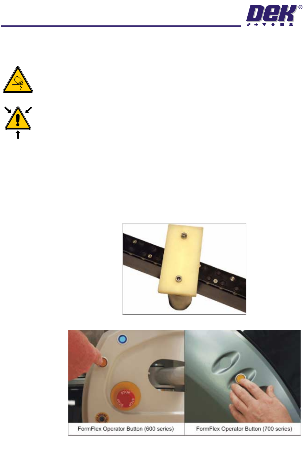
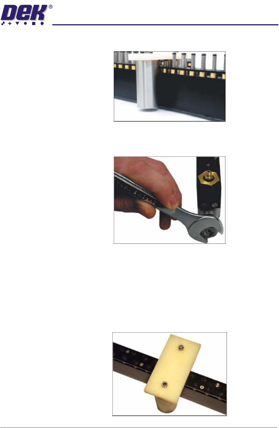
4. Place the setting weight over the tooling module, covering 6 FormFlex pins.
5. Press the amber operator button on the machine front cover.
NOTE
The amber operator button flashes during setup and changes to continuous
amber when complete.
TECHNICAL REFERENCE
ADJUSTMENTS AND SETTINGS
Chapter Issue 4 Jun 04 FormFlex Tooling Manual 1.7
6. If the setting weight has been lifted from the manual tooling plate, press the
green reset button located inside the front cover and go to Step 13.
7. If the assembly has not been lifted, press the green reset button located
inside the front cover.
8. Using a 17mm spanner remove the spring tension screw locknut.
9. Using a flat bladed screwdriver, adjust the spring tension screw a half turn
clockwise.
10.Press the amber operator button on the machine front cover to raise the
FormFlex pins.
11. If the setting weight has been lifted from the manual tooling plate, press the
green reset button located inside the front cover and go to Step 13.
12.Press the green reset button located inside the front cover and repeat Steps
9 - 11 until the setting weight has been raised.
13.Adjust the position of the setting weight to cover five FormFlex pins.
1.8 FormFlex Tooling Manual Chapter Issue 4 Jun 04
TECHNICAL REFERENCE
ADJUSTMENTS AND SETTINGS
14.Press the amber operator button on the machine front cover to raise the
FormFlex pins.
15.If the setting weight has not been lifted off of the tooling plate when all the
FormFlex pins have been raised, the pin pressure in the tooling module
under test is now correct, go to Step 18.
16.If the setting weight has been raised by the five FormFlex pins, press the
green reset button. Using a flat bladed screwdriver adjust the spring tension
screw a quarter turn anti-clockwise.
17.Repeat Steps 14 - 16 until the setting weight fails to lift when all the FormFlex
pins have raised.
18.Repeat Steps 4 and 5 to ensure that the setting weight will still be lifted by 6
pins.
19.If adjustment was made, lock the spring tension screw locknut loosened in
Step 8.
20.Press the green reset button located inside the front cover.
21.Repeat the procedure for the remaining modules.
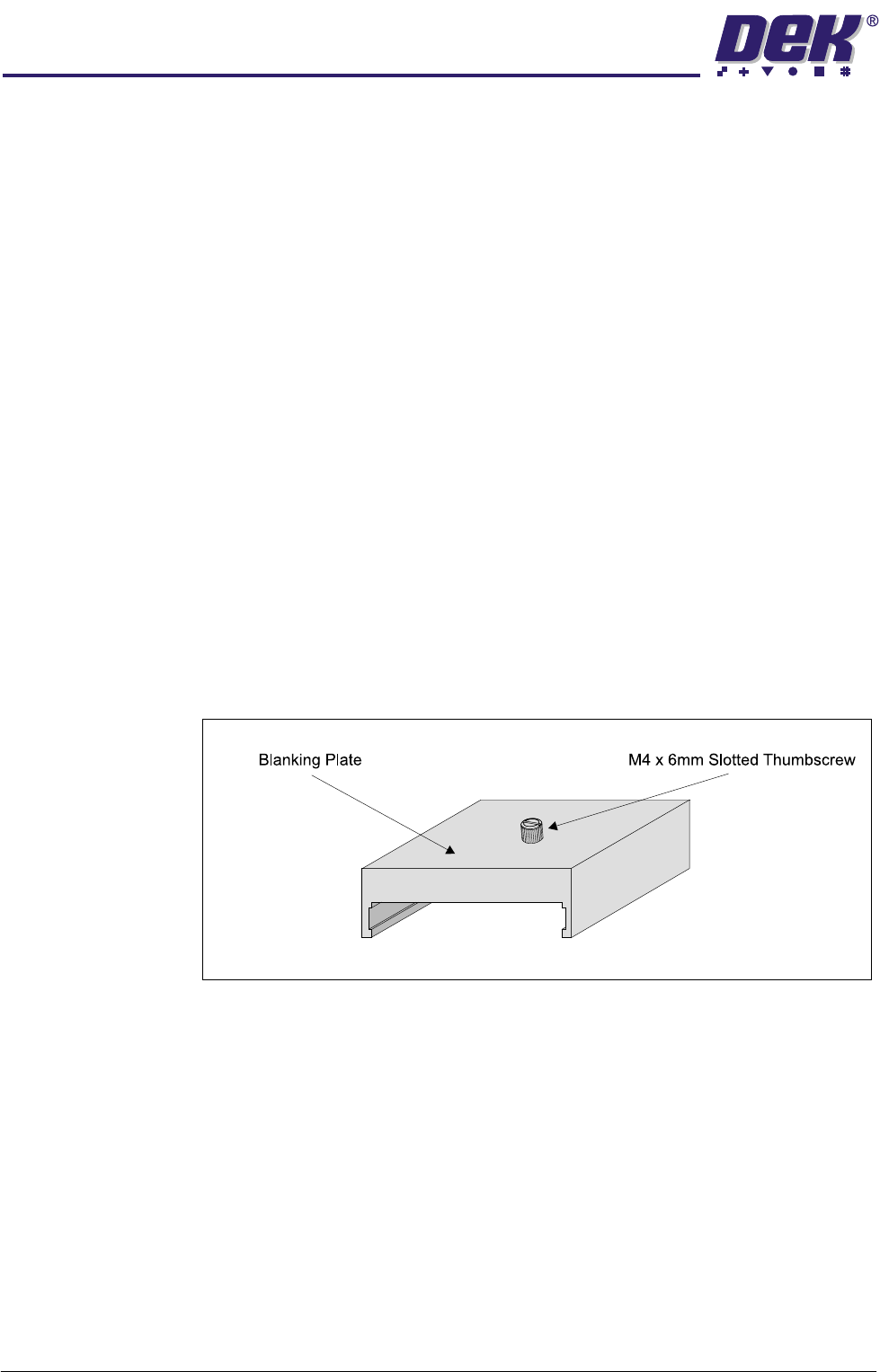
Blanking Plate Kit To improve gasketting when printing thin flexible boards, a set of blanking plates
are provided. These plates are clamped to the top of the tooling modules over
FormFlex pins outside the print area. The plates prevent the FormFlex pins not
supporting the board and squeegee/ProFlow head from rising as the print stroke
is performed.
Figure 1-4 Blanking Plate