Formflex Manual.pdf - 第18页
TECHNI CAL R EFEREN CE REPLACEM ENT PROC EDURES Chapter Issue 4 Jun 04 FormFlex Tooling M anual 1.11 6. Connect 4mm pneumati c tubing fro m the fluid cut- off v alve of the t ooling modules to the overri de manifold as s…
1.10 FormFlex Tooling Manual Chapter Issue 4 Jun 04
TECHNICAL REFERENCE
REPLACEMENT PROCEDURES
REPLACEMENT PROCEDURES
Fitting FormFlex Tooling
WARNING
COMPRESSED AIR. COMPRESSED AIR SHOULD NEVER IMPINGE UPON THE
BODY. PORTS, PIPES, ETC MUST NEVER BE BLOCKED BY HAND. BEFORE
CONNECTING ANY PNEUMATIC EQUIPMENT TO A COMPRESSED AIR SUPPLY,
ALL MOUNTINGS, FITTINGS, PIPEWORK AND ELECTRICAL CONNECTIONS
SHOULD BE REMOVED FOR SAFETY. NO PIPEWORK ALTERATIONS OR
REMOVAL OF FITTINGS SHOULD BE ATTEMPTED WITH AIR SUPPLIES
CONNECTED.
WARNING
BOARD CLAMPS. EXTREME CARE MUST BE EXERCISED WHEN WORKING IN
THE TOOLING AREA OF THE MACHINE TO AVOID INJURY. THE FOILS ON THE
FRONT AND REAR BOARD CLAMPS ARE VERY SHARP.
1. Gain access to the manual tooling plate.
2. Power down the machine.
3. Ensure the front FormFlex tooling module has the two registration grub
screws fitted to the base of the unit. Locate the grub screws in the holes in
the front edge of the manual tooling plate.
NOTE
When placing the tooling modules on the manual tooling plate, ensure that
the fluid cut-off valve is on the left and the pneumatic connection is on the
right.
4. The remaining tooling modules can be configured to suit the product to be
printed. The tooling modules can be staggered in the X axis and/or spread
evenly in the Y axis to fully support the product to be printed.
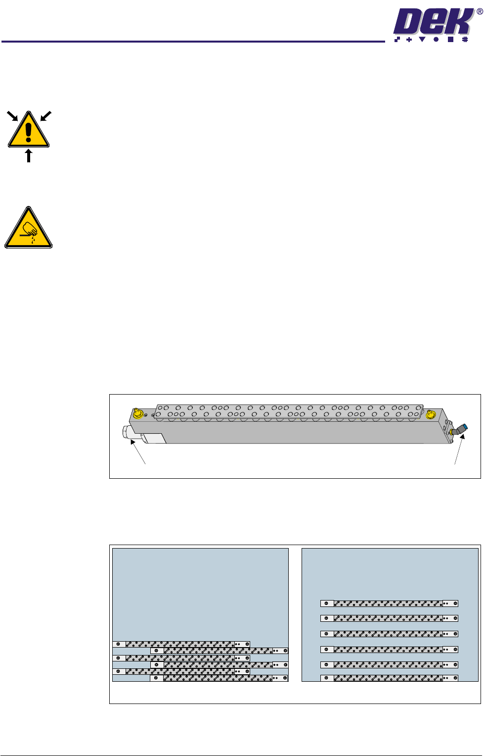
5. Connect 4mm pneumatic tubing from the pneumatic connector of the tooling
modules to the sequencing manifold as shown in the figure below.
Fluid Cut-Off Valve Pneumatic Connection
Plan View on Manual Tooling Plate
6
6
5
5
4
4
3
3
2
2
1
1
TECHNICAL REFERENCE
REPLACEMENT PROCEDURES
Chapter Issue 4 Jun 04 FormFlex Tooling Manual 1.11
6. Connect 4mm pneumatic tubing from the fluid cut-off valve of the tooling
modules to the override manifold as shown in the figure below.
7. Power up the machine.
8. Carry out FormFlex Pin Pressure procedure in Adjustments and Settings
section of this chapter.
9. Carry out FormFlex Setup in the Machine Programming chapter of this
manual.
Removing FormFlex Tooling
WARNING
COMPRESSED AIR. COMPRESSED AIR SHOULD NEVER IMPINGE UPON THE
BODY. PORTS, PIPES, ETC MUST NEVER BE BLOCKED BY HAND. BEFORE
CONNECTING ANY PNEUMATIC EQUIPMENT TO A COMPRESSED AIR SUPPLY,
ALL MOUNTINGS, FITTINGS, PIPEWORK AND ELECTRICAL CONNECTIONS
SHOULD BE REMOVED FOR SAFETY. NO PIPEWORK ALTERATIONS OR
REMOVAL OF FITTINGS SHOULD BE ATTEMPTED WITH AIR SUPPLIES
CONNECTED.
WARNING
BOARD CLAMPS. EXTREME CARE MUST BE EXERCISED WHEN WORKING IN
THE TOOLING AREA OF THE MACHINE TO AVOID INJURY. THE FOILS ON THE
FRONT AND REAR BOARD CLAMPS ARE VERY SHARP.
1. Gain access to the manual tooling plate.
2. Power down the machine.
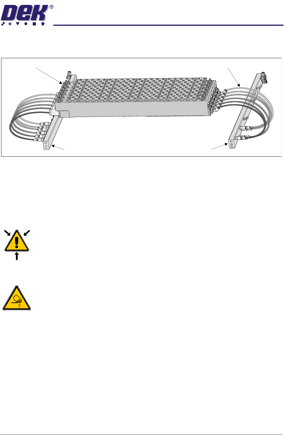
3. Disconnect and remove the 4mm pneumatic tubing from the sequencing
manifold to the tooling modules.
4. Disconnect and remove the 4mm pneumatic tubing from the override man-
ifold to the tooling modules.
5. Remove the tooling modules from the manual tooling plate.
Override Manifold
Tooling Modules
Sequencing Manifold
4mm Pneumatic Tubing
1.12 FormFlex Tooling Manual Chapter Issue 4 Jun 04
TECHNICAL REFERENCE
FAULT FINDING
FAULT FINDING
Fault Analysis
WARNING
BOARD CLAMPS. EXTREME CARE MUST BE EXERCISED WHEN WORKING IN
THE TOOLING AREA OF THE MACHINE TO AVOID INJURY. THE FOILS ON THE
FRONT AND REAR BOARD CLAMPS ARE VERY SHARP.
WARNING
COMPRESSED AIR. COMPRESSED AIR SHOULD NEVER IMPINGE UPON THE
BODY. PORTS, PIPES, ETC MUST NEVER BE BLOCKED BY HAND. BEFORE
CONNECTING ANY PNEUMATIC EQUIPMENT TO A COMPRESSED AIR SUPPLY,
ALL MOUNTINGS, FITTINGS, PIPEWORK AND ELECTRICAL CONNECTIONS
SHOULD BE REMOVED FOR SAFETY. NO PIPEWORK ALTERATIONS OR
REMOVAL OF FITTINGS SHOULD BE ATTEMPTED WITH AIR SUPPLIES
CONNECTED.
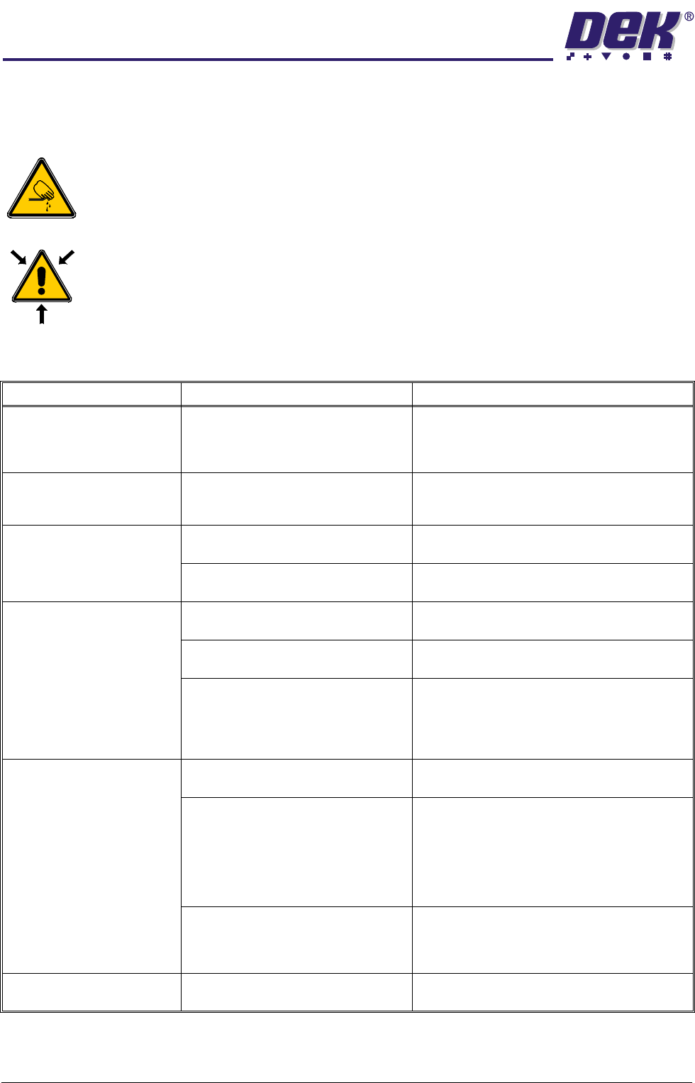
Symptom Possible Causes Possible Solutions
After periods of inactivity,
some pins not being raised in
one or more tooling modules
during initial setup.
Lack of lubrication of pin seals. Carry out Pins Remaining Down later in this
section.
Board not being fully sup-
ported during printing causing
print process issues.
1. Excessive air in tooling module. 1. Carry out Module Air Check later in this
section.
No pins are raised in any tool-
ing module.
1. Failure of machine air supply. 1. Check the air supply reading at the machine
filter regulator assembly.
2. Air leak between machine interface
FormFlex sequencer assembly.
1. Check the connections between the units,
ensuring no air leaks are present.
When FormFlex is reset,
some FormFlex pins in a mod-
ule remain raised.
1. Sticky FormFlex pins. 1. Carry out Pins Remaining Up later in this
section.
2. Sticky fluid cut-off valve. 1. Carry out Pins Remaining Up later in this
section.
3. Insufficient vacuum. 1. Check the connections between the units,
ensuring no air leaks present.
2. Check air supply to venturi vacuum unit on the
FormFlex sequencer assembly. If air present,
reject the FormFlex sequencer assembly.
All pins not being raised in one
tooling module.
1. Air leak between sequencer mani-
fold and tooling module.
1. Check the connections between the units,
ensuring no air leaks present.
2. Supply pipe to tooling module incor-
rectly connected.
1. Check for correct pipe connections between
the sequencer manifold and tooling module.
2. Confirm pipe connections by disconnecting
the supply pipe to the tooling module at the
module. Press the operator button, air should
escape from the pipe at the relevant point in the
setup sequence.
3. Sticky FormFlex pins. 1. If no fault found, carry out Pins Remaining
Down later in this section.
2. If pins fail to rise, contact DEK Customer
Support.
Excessive oil found leaking
from tooling module.
1. Contact DEK Customer Support.