Formflex Manual.pdf - 第15页
1.8 FormFlex Tooling Manual Chapter Issue 4 Jun 04 TECHNIC AL RE FERENCE ADJUS TMENT S AND SET TINGS 14. Press the amber operato r button on t he machine front cov er to rais e the FormFlex p ins. 15. If the sett ing wei…
TECHNICAL REFERENCE
ADJUSTMENTS AND SETTINGS
Chapter Issue 4 Jun 04 FormFlex Tooling Manual 1.7
6. If the setting weight has been lifted from the manual tooling plate, press the
green reset button located inside the front cover and go to Step 13.
7. If the assembly has not been lifted, press the green reset button located
inside the front cover.
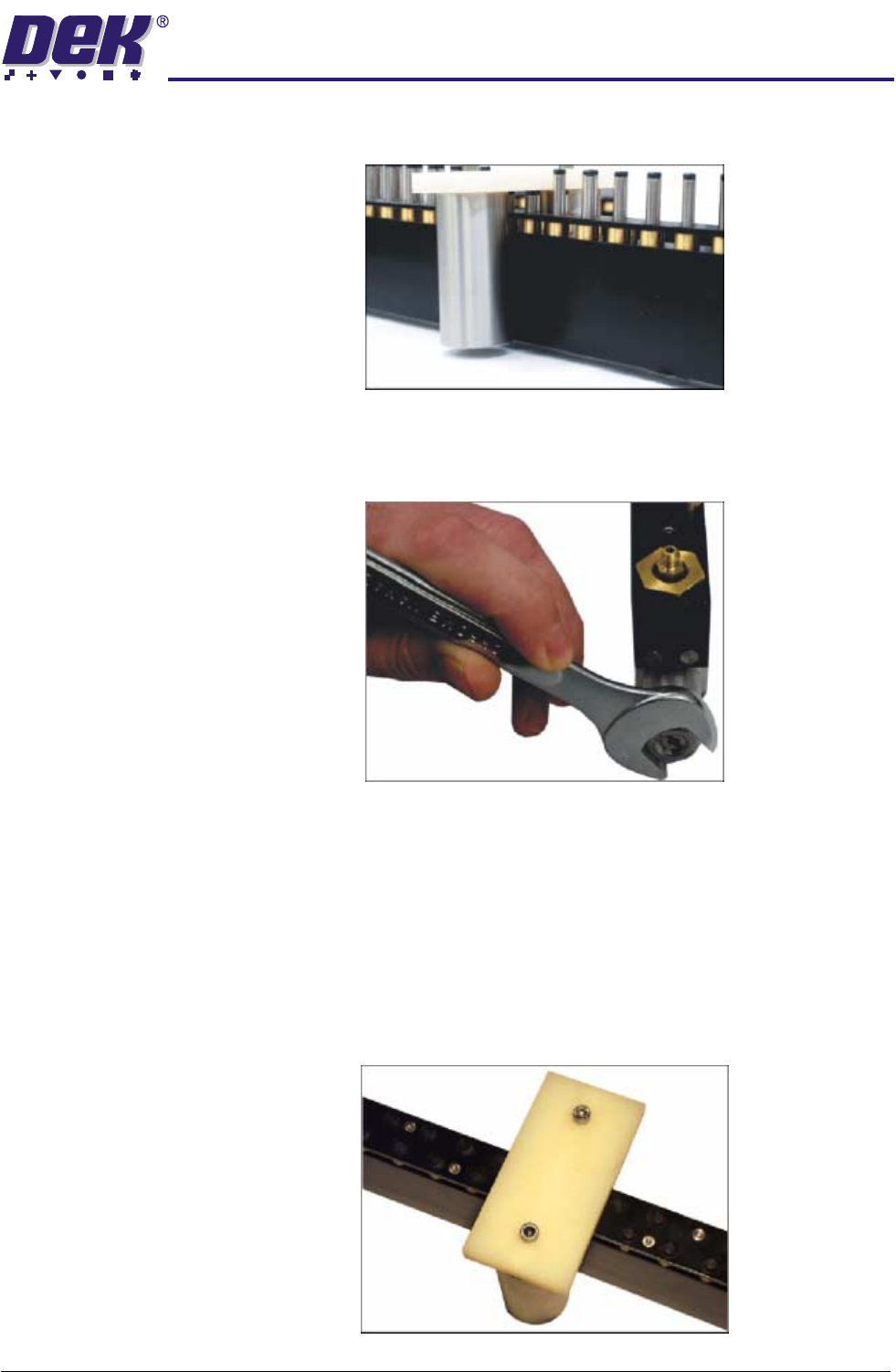
8. Using a 17mm spanner remove the spring tension screw locknut.
9. Using a flat bladed screwdriver, adjust the spring tension screw a half turn
clockwise.
10.Press the amber operator button on the machine front cover to raise the
FormFlex pins.
11. If the setting weight has been lifted from the manual tooling plate, press the
green reset button located inside the front cover and go to Step 13.
12.Press the green reset button located inside the front cover and repeat Steps
9 - 11 until the setting weight has been raised.
13.Adjust the position of the setting weight to cover five FormFlex pins.
1.8 FormFlex Tooling Manual Chapter Issue 4 Jun 04
TECHNICAL REFERENCE
ADJUSTMENTS AND SETTINGS
14.Press the amber operator button on the machine front cover to raise the
FormFlex pins.
15.If the setting weight has not been lifted off of the tooling plate when all the
FormFlex pins have been raised, the pin pressure in the tooling module
under test is now correct, go to Step 18.
16.If the setting weight has been raised by the five FormFlex pins, press the
green reset button. Using a flat bladed screwdriver adjust the spring tension
screw a quarter turn anti-clockwise.
17.Repeat Steps 14 - 16 until the setting weight fails to lift when all the FormFlex
pins have raised.
18.Repeat Steps 4 and 5 to ensure that the setting weight will still be lifted by 6
pins.
19.If adjustment was made, lock the spring tension screw locknut loosened in
Step 8.
20.Press the green reset button located inside the front cover.
21.Repeat the procedure for the remaining modules.
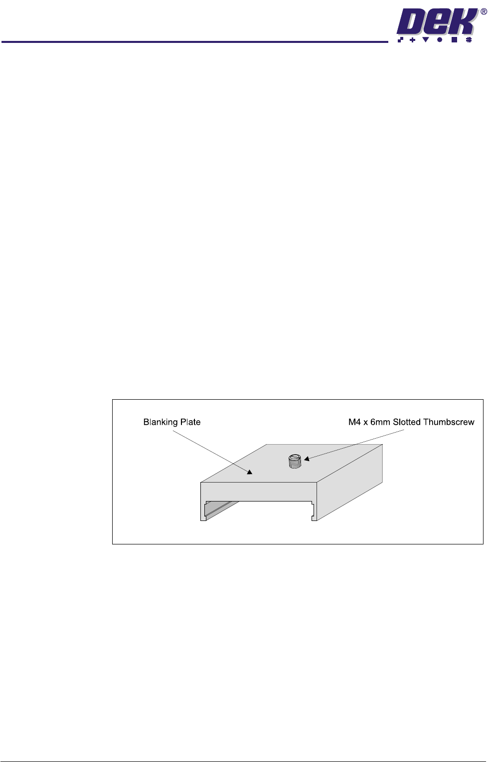
Blanking Plate Kit To improve gasketting when printing thin flexible boards, a set of blanking plates
are provided. These plates are clamped to the top of the tooling modules over
FormFlex pins outside the print area. The plates prevent the FormFlex pins not
supporting the board and squeegee/ProFlow head from rising as the print stroke
is performed.
Figure 1-4 Blanking Plate
TECHNICAL REFERENCE
ADJUSTMENTS AND SETTINGS
Chapter Issue 4 Jun 04 FormFlex Tooling Manual 1.9
The blanking plates are available in the following lengths:
• 100mm - Disables ten FormFlex pins
• 50mm - Disables five FormFlex pins
• 12mm - Disables one/two FormFlex pins
If the blanking plates are used within the board support area the component
underboard clearance is reduced to 3.5mm. However, the component under-
board clearance can be increased if the slotted thumbscrew is replaced with an
appropriate size grub screw.
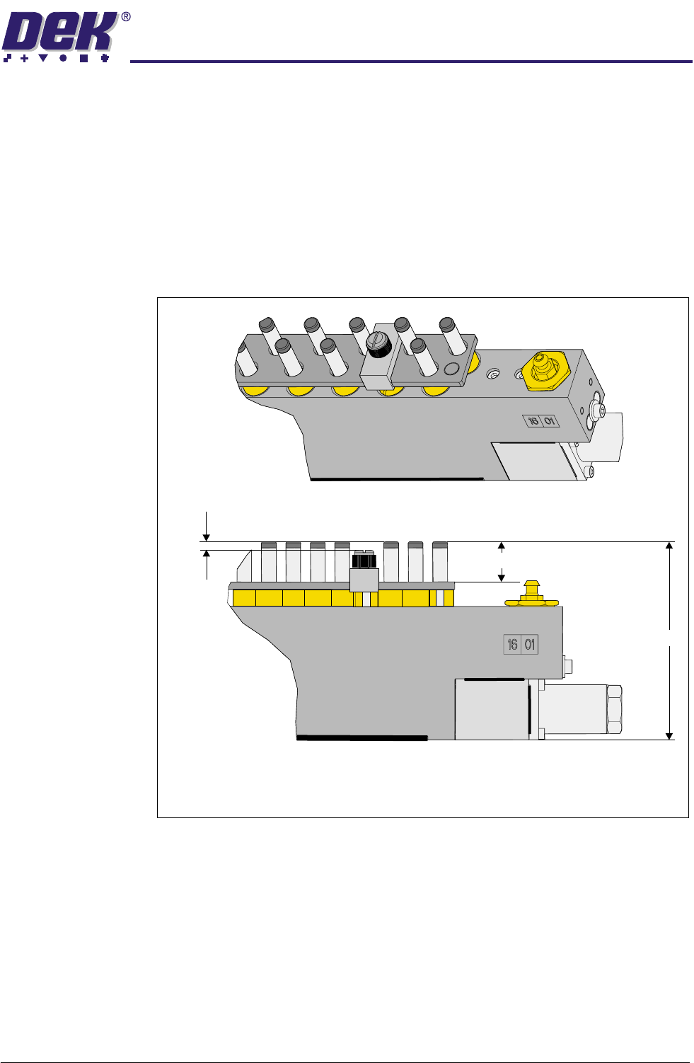
Figure 1-5 Board Under Clearance - Blanking Plate Fitted
During product setup, the appropriate sized blanking plates are slid onto the
tooling module outside the area of the squeegees/ProFlow and clamped in
place using the M4 x 6mm slotted thumb screw.
Isometric View on Tooling Module - Blanking Plate Fitted
A - Standard Tooling Height - 81mm
B - Component Under Board Clearance - 15mm
C - Component Under Board Clearance - Blanking Plate Fitted - 3.5mm
A
B
C