WPC an:on SIPLACE SX1:SX2 Montageanleitung : Assembly Instructions.pdf - 第69页
5 Appendix Mo nt ag ea nl ei tu ng / A ss em bl y In st ru ct io ns W PC a n/ on S IP LA CE S X1 /S X2 - 0 3/ 20 25 69 5 Appendix 5.1 Excerpts from the Service Manual The following chapters are excerpts from the service …

4 Operator Tasks
68 Montageanleitung / Assembly Instructions WPC an/on SIPLACE SX1/SX2 - 03/2025
5 Appendix
Montageanleitung / Assembly Instructions WPC an/on SIPLACE SX1/SX2 - 03/2025 69
5 Appendix
5.1 Excerpts from the Service Manual
The following chapters are excerpts from the service manual. For more information, refer to the full
service manual for your machine.
5.1.1 Downholder
Overview downholder (new design) - for COTi60 [03294435-xx]
Fig.22: Downholder – outside position
Outside position:
1. Downholder left [03296161-xx]
2. Downholder right [03296153-xx]
3. ISO4762 M6x22 [03043127‑xx]
Downholder-Pin [03094146‑xx]
4. ISO4762 M8x30 [03042587‑xx]
Fig.23: Downholder – inside position
Inside position
1. Downholder left [03296161-xx]
2. Downholder right [03296153-xx]
3. ISO4762 M6x22 [03043127‑xx]
Downholder-Pin [03094146‑xx]
4. ISO4762 M8x30 [03042587‑xx]
5. Spacer [03307707‑xx]
ISO4762 M8x30 [03042587‑xx]
5 Appendix
70 Montageanleitung / Assembly Instructions WPC an/on SIPLACE SX1/SX2 - 03/2025
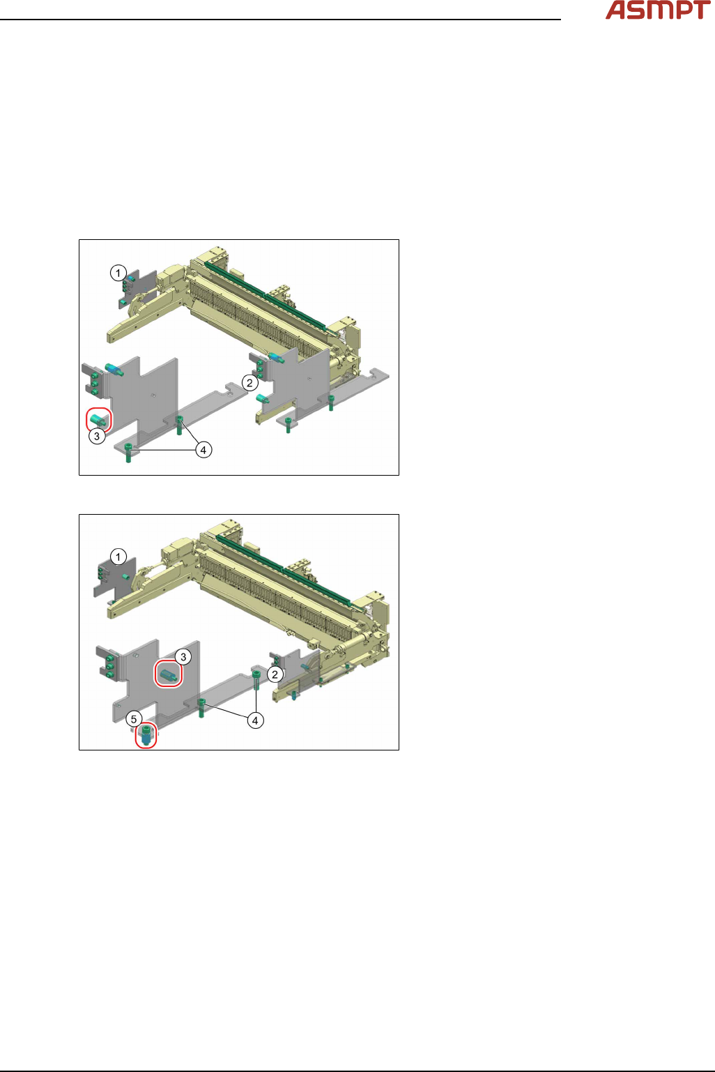
Overview downholder (previous design) - for COTi60 [03059353-xx]
Fig.24: Downholder
1 Pin DIN6325-10-M6x30-St [00358814-xx]
at position inside
2 Pin DIN6325-10-M6x30-St [00358814-xx]
at position outside
3 Docking aid 4 Screw ISO4762-M8x40-A2-70
[03042589-xx]
5 Screw ISO4762-M8x40-A2-70
[03042589-xx]
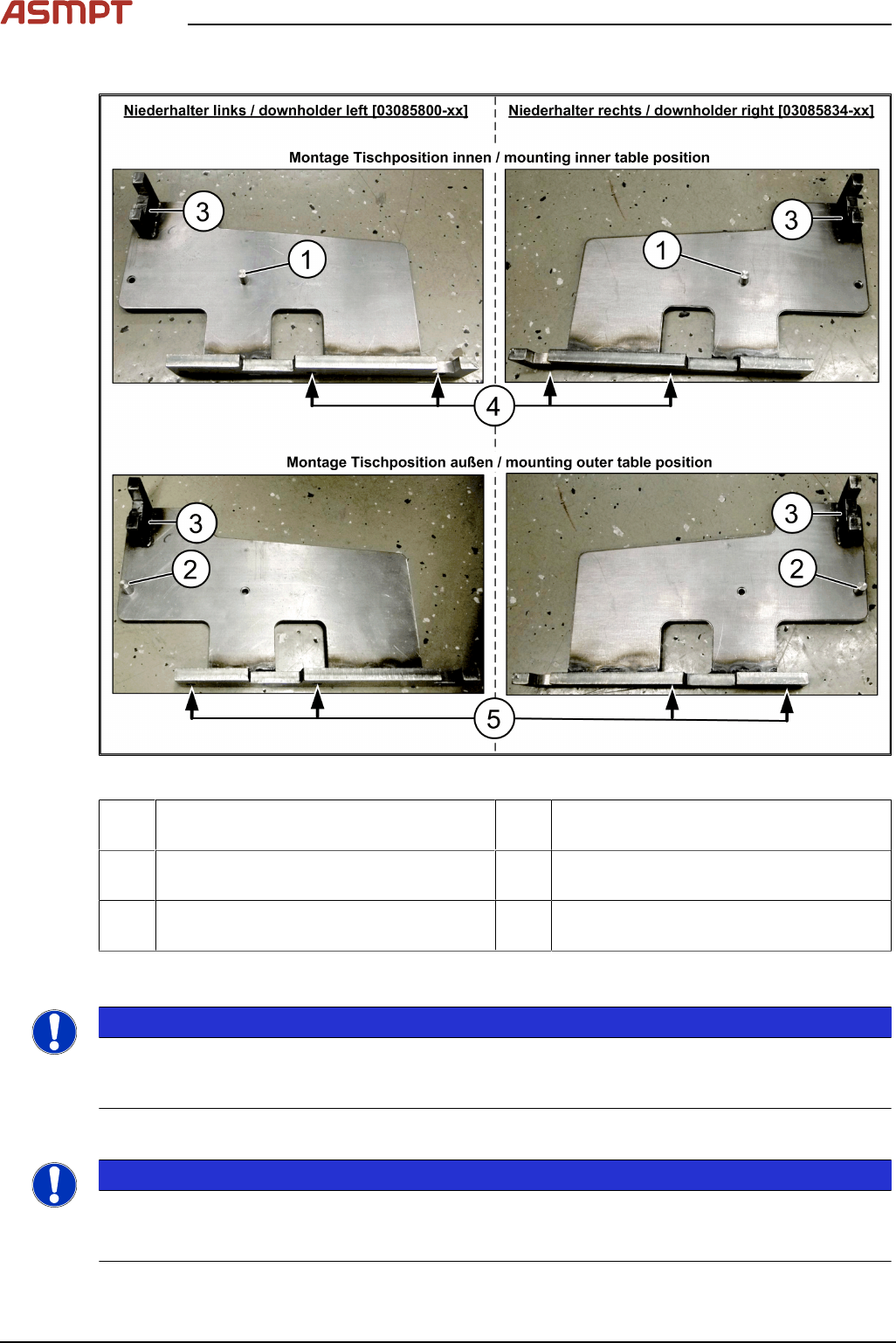
5.1.1.1 Fitting the Downholder
NOTICE
Example diagram
The assembly of the downholder is shown below using the example of the downholder device (previ-
ous design). The assembly of the downholder(new design) needs to be carried out accordingly.
Preparing the downholder
NOTICE
Only when table position changed
The downholder pin only needs to the converted if the table position inside/outside has been
changed.