00197191-02_IM_SIPLACE_Pro_10.1_EN.pdf - 第16页
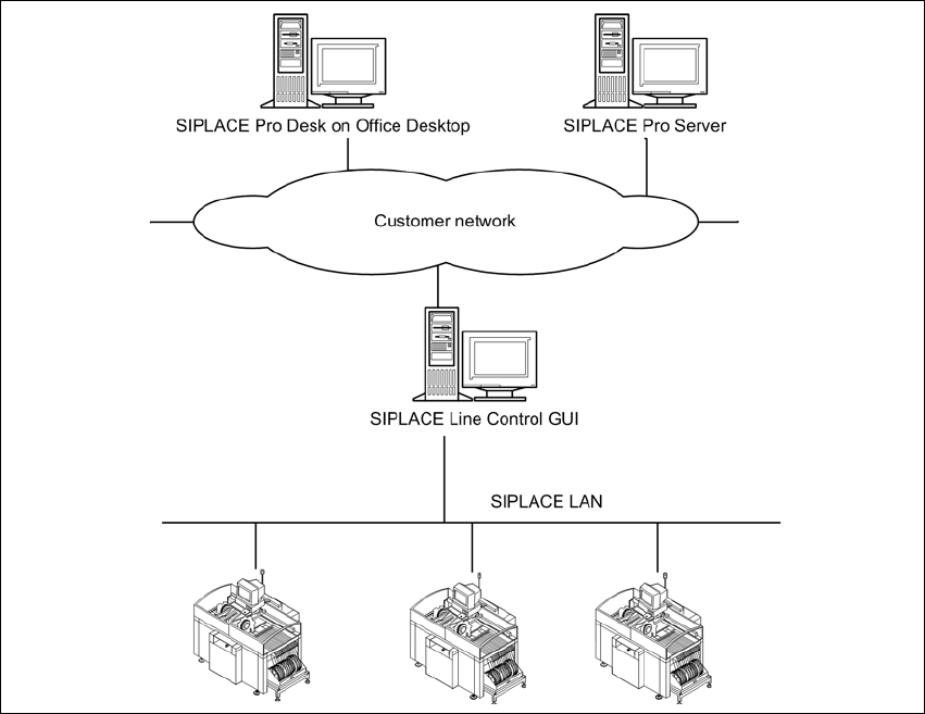
Installation Manual 2 System components and configur ations SIPLACE Pro 10.1 Edition 09/2012 14 2.2.1.2 Physical Layout 2 Fig. 2.2 - 2 St andard Configuration - Physical Layout 2.2.2 Characteristics – SIPLACE Pro Server …
2 System components and configurations Installation Manual
Edition 09/2012 SIPLACE Pro 10.1
13
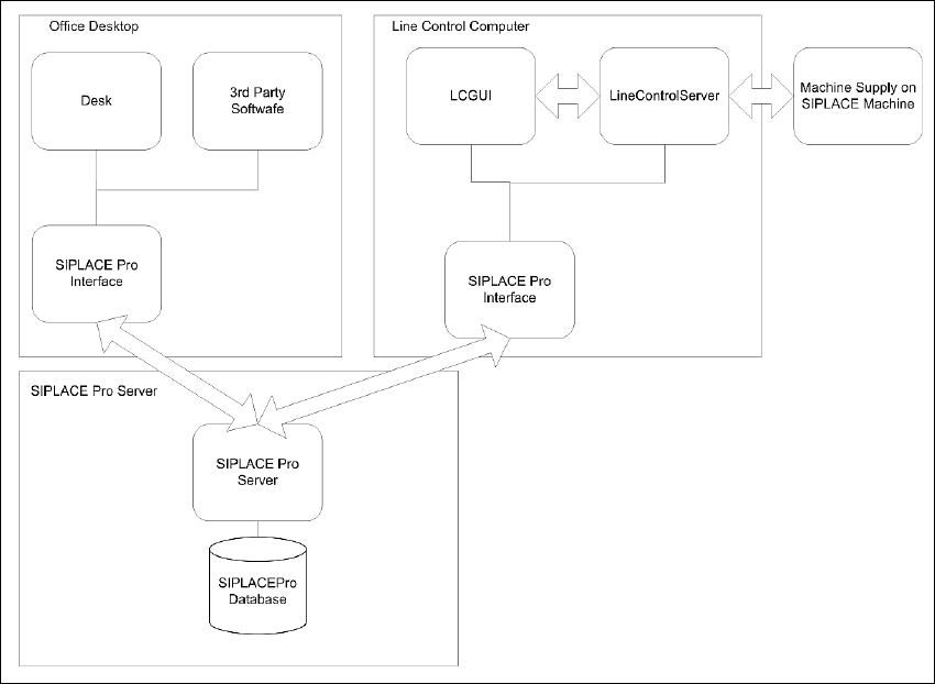
2.2.1.1 Logical Layout
When the participating computer is well integrated into the customer network, then it is possible
to split SIPLACE Pro client components onto different computer to suit the customer needs. Here
we have a dedicated SIPLACE Pro Server and Client operating as Programming System or Line
Control System.
2
Fig. 2.2 - 1 Standard Configuration - Logical Layout
Installation Manual 2 System components and configurations
SIPLACE Pro 10.1 Edition 09/2012
14
2.2.1.2 Physical Layout
2
Fig. 2.2 - 2 Standard Configuration - Physical Layout
2.2.2 Characteristics
– SIPLACE Pro Server will be installed on Windows Server Version.
– SIPLACE Pro Server will be migrated into customer domain configuration.
– SIPLACE Pro Client machines can be connected, if they are either in the same domain or in
a domain with a trust relation to the domain where the server resides.
– The SIPLACE Pro server must be part of the customer network.
– A WINS or DNS Server from the customer network infrastructure is necessary.
– If the customer network is segmented by routers, it must be possible to integrate the routing
device into customer routing configuration.
– Security inside SIPLACE Pro is possible.
– Operation of the SIPLACE Pro systems depends on the customer infrastructure.
– Using a router of a Windows PC as a routing device to separate network traffic from the SI-
PLACE LAN from the customer LAN.
2 System components and configurations Installation Manual
Edition 09/2012 SIPLACE Pro 10.1
15
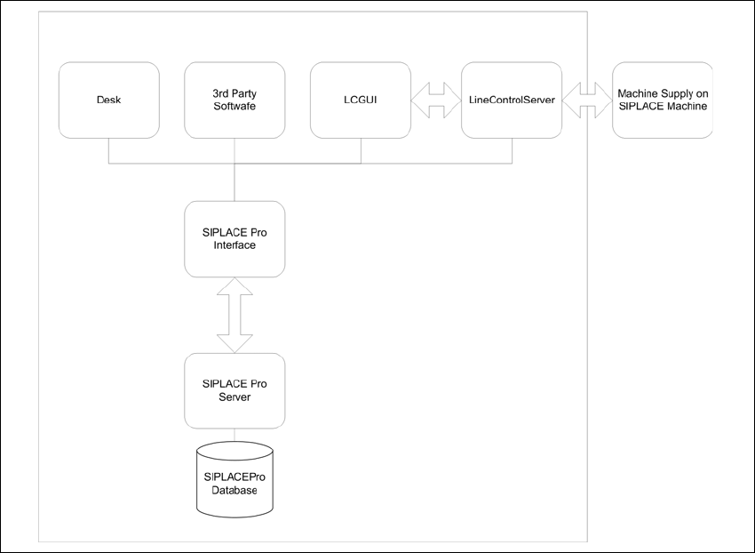
2.3 Stand-alone Configuration
Install all software components on one computer. This computer then functions as both server and
client. Optionally a second connection to the customer's network can be established via a second
network card.
2.3.1 Logical Layout
2
Fig. 2.3 - 1 Stand-alone Configuration - Logical Layout