00196624-04_Service Manual WPC5_6_EN_01-2019.pdf - 第62页
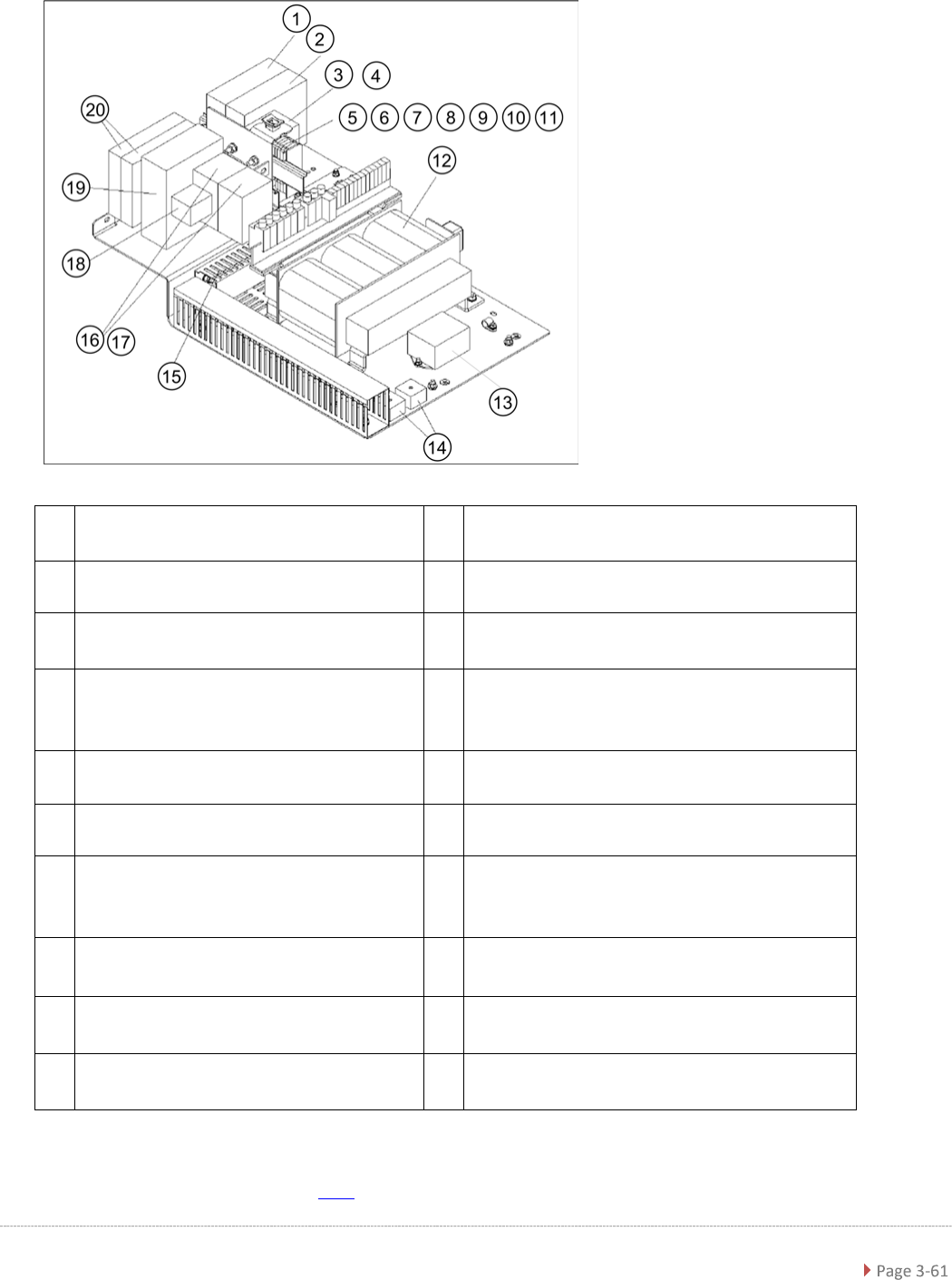
Service Ma nual W PC5 / WPC6 Non-Stop-Module Elekt rics [0305779 7-xx] Part s Quant ity Name It em no. 1 Table plate electrics 03 0 5 7 79 8 - xx 1 Power cable load ax is 03 0 5 6 95 0 - xx 1 Signal cable load axis 03 0 …
Service Manual WPC5 / WPC6
3.6.4.3 Power Supply WPC6
1
Inrush current limitation board WPC NS
[03056232-xx]
11 End plate, gray, type 282-311 [00372782-xx]
2
Inrush current limitation board WPC
[03047752-xx]
12 Transformer WPC5 [03057556-xx]
3
Contactor 3RT10 15-2BM42 [03048357-
xx], K4
13
Line filter for 3-phase system 10A [03048582-
xx]
4
Suppression diode for contactors DC150-
250V [03048925-xx] discontinued
,
Surge suppressor diode 3RT2 150-250V
LED [03171141-xx] successor; on K4
14 Rectifier bridge 800V / 25A [03048868-xx]
5
Ground terminal block 4-cond 280-677
[00323829-xx]
15
Cable duct 40X40mm GYT1-40X40
[03008823-xx]
6
Through terminal block GY 4-con. 280-
633 [00323828-xx]
16
Contactor 3RT10 15-1BB42 [03048563-xx],
K2 und K3
7
Adjacent jumper 280-402 [0035338-xx]
17
Suppression diode for contactors DC 24-70V
[00342396Sxx]
discontinued
,
Surge suppressor diode 3RT2 24V-70V LED
[03171140-xx] successor; on K3
8
End plate 2.5mm orange 280-315
[00323836-xx]
18
Auxil. switch block 3RH19/2pole/1NC+1NO
[03048564-xx], on K3
9
Screwless end stop 6 m 249-116
[00356396-xx]
19
Emergency stop switchgear 3TK2828-1BB41
[00372649-xx], K1
10
Fuse clamp 10A (6.3X32) 282-128
[00372781-xx]
20
Emergency-Stop and protective door
monitoring [03056745-xx], K5 and K6
For a detailed overview of the connections, see "3.7.1.3 Detailed Connections for Limit Switches,
Sensors and Light Barriers" [➙ 3-71].

Service Manual WPC5 / WPC6
Non-Stop-Module Elektrics [03057797-xx]
Parts
Quantity
Name
Item no.
1
Table
plate electrics
03
0
5
7
79
8
-
xx
1
Power cable load axis
03
0
5
6
95
0
-
xx
1
Signal cable load axis
03
0
5
6
94
8
-
xx
1
Reference point proximity switch load axis
03
0
5
6
94
7
-
xx
1 ble: operat. button with signal light 03057602-xx
1 Cable: Safety sensor loading flap 03057600-xx
1 Cable: safety sensor hand guard 03057601-xx
1 Cable: lifting magnet safety flap closing 03057603-xx
1 Cable: lifting magnet safety flap opening 03057604-xx
1 Crash light barrier normal components load
axis
03057012-xx
1
Crash light barrier hi
gh components load axis
03
0
5
7
29
1
-
xx
1
Cable:
sensor safety flap open
03
0
5
7
59
8
-
xx
1
Cable: sensor tray correctly inserted
03
0
5
7
59
9
-
xx
1
Cable: sensor tray detection load axis
03
0
7
1
45
3
-
xx
Service Manual WPC5 / WPC6
3.6.5 Power Supply Unit
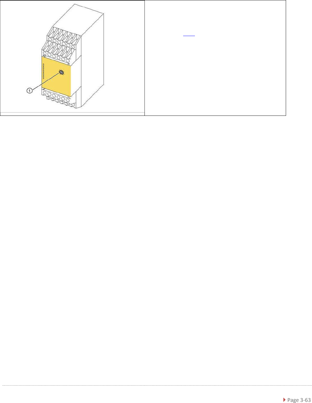
3.6.5.1 Replacing the Protective Contactor Combination (SSK)
Spare Part
• Protective contactor combination (SSK) 3TK2828-
1BB41 [00372649-xx]
Removal / Installation
➢ Label all connections for easier installation later.
➢ Unplug all connections from the protective contactor combination.
➢ Lever the protective contactor combination off the mounting rail.
➢ Connect the new protective contactor combination to the mounting rail and restore the
electrical connections..
Settings
➢ Adjust the setting screw (1) to a value of 0.5 (seconds). If the value is set too high, an error
message will be issued.
➢ Seal the setting screw with locking varnish.
The protective contactor combination (SSK) is
located at the front of the electrical unit (see "3.6.2
Overview"[➙ 3-46]).
1. setting screw