00196624-04_Service Manual WPC5_6_EN_01-2019.pdf - 第92页
Service Ma nual W PC5 / WPC6 For the light barrier : The status of the crash light barr ier will be shown by t he integrated LED: • Red LED shines = not triggered (nor mal mode) • Red LED does not shi ne = triggered (th …
Service Manual WPC5 / WPC6
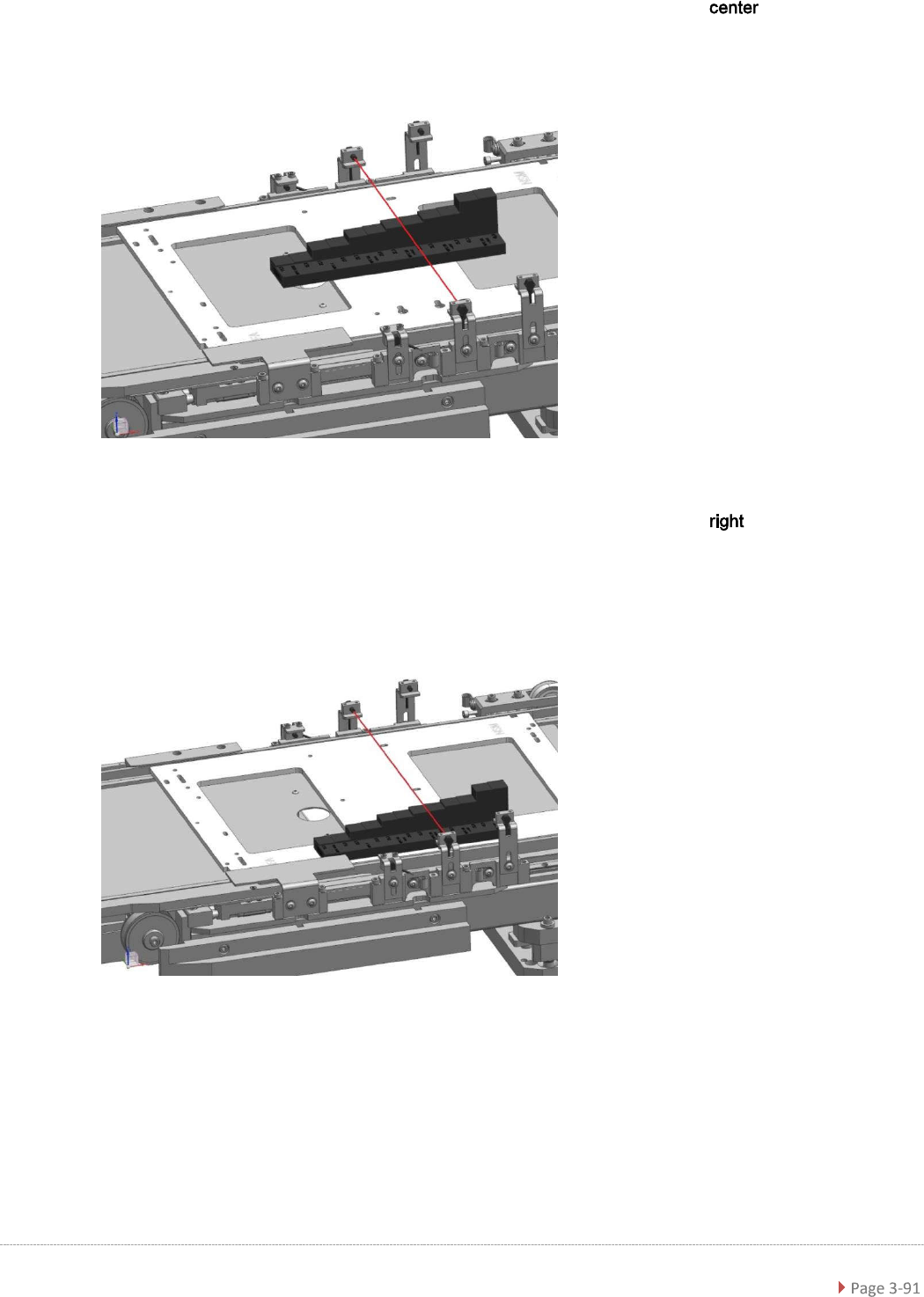
➢ Now plug the "Adjustment-Jig crash-LS-WPC4-6 (step)” [03093895-01] to the position
of the base plate.
➢
Move the base plate with the “step gauge” slowly forward on the feed axis.
The Light barrier must be exactly at the level of the respective stages pair position.
.
➢ Now plug the "Adjustment-Jig crash-LS-WPC4-6 (step)” [03093895-01] to the position
of the base plate.
➢
Move the base plate with the “step gauge” slowly forward on the feed axis.
The Light barrier must be exactly at the level of the respective stages pair position.

Service Manual WPC5 / WPC6
For the light barrier :
The status of the crash light barrier will be shown by the integrated LED:
• Red LED shines = not triggered (normal mode)
• Red LED does not shine = triggered (the light beam is interrupted - crash situation)
• Green LED shines = ready for operation/stability display (optimum light barrier setting)
• Green LED does not shine = ready for operation/stability display (no optimum light barrier
setting)
• LED shines red and green = correct setting (the laser beam is not interrupted)
For the light barrier :
The Status of the ligth barrier is shown on the display (7 segment) of the control unit, as well as
with the LED beside the display.
• LED on (orange) = normal function (light beam is interrupted)
• LED off = activated (light beam is interrupted – Crash situation)
The displayed value is in normal function higher than 2500.
The threshold, at which the unit switches (LED gets off), is at about 500.
=> at 100% interruption = 0,
Step 1: setting the height
➢ Position the setting gauge with the throughout height setting on the waffle-pack tray carrier,
before the relevant transmitter/receiver:
⇨ Description signals (LED, values), see above.
➢ Move the gauge or the waffle-pack tray carrier to the trigger height setting.
➢ Check whether the crash light barrier beam is interrupted at the trigger height setting or not.
➢ Place the "Setting gauge crash WPC4 LS-6 (level)" [03093895-02] on the other two
positions. The crash beam sensor must trigger safe here.
➢ Repeat the steps described until the crash light barriers are set to the correct height and
switch reliably at all trigger points over the entire area.
Step 2: function test
➢ Check that the correct outputs are switched.
Go to the main software view and open the menu function:
check that the or
option is enabled
Service Manual WPC5 / WPC6
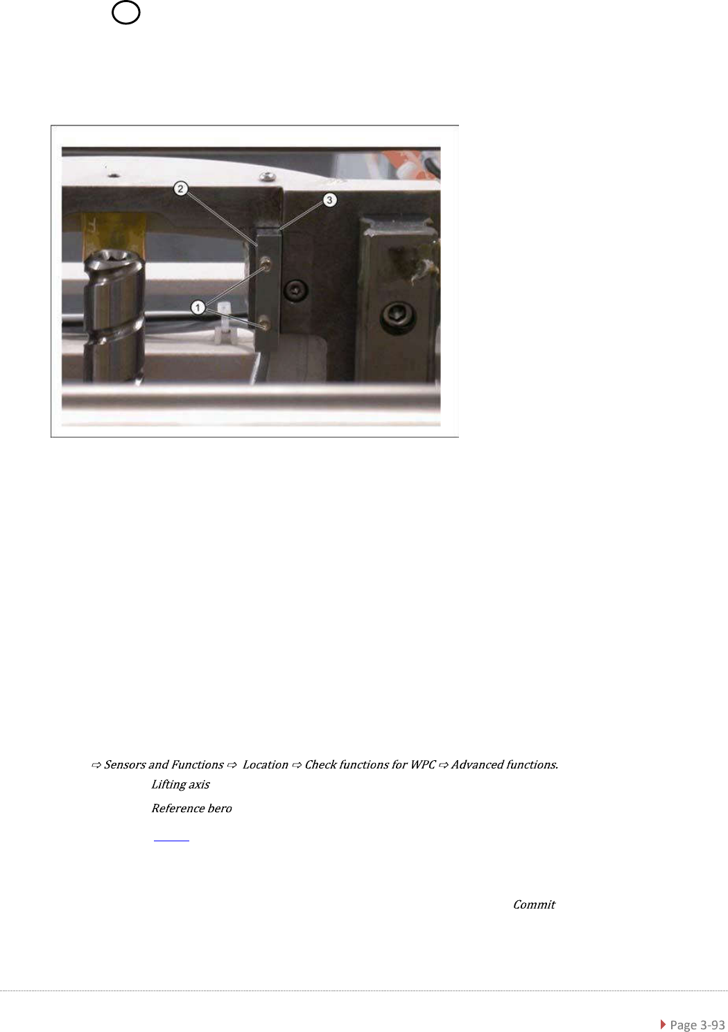
3.7.8 Sensor 6 Reference Sensor "Lifting axis“
Spare Part
• Reference point proximity switch for lifting axis [03047278-01]
Removal / Installation
➢ Loosen the two fastening screws (1) on the reference sensor.
➢ Loosen the cable clamps and remove the cable ties.
➢ Unthread the connection cable as far as the control unit back plane and unplug it from the
terminal strip.
➢ Fit the reference sensor so that the sensor surface (2) points to the side.
➢ Align the reference sensor parallel to the right-hand and top stopper edges (3).
➢ Restore the electrical connection and fix the connection cable into place.
Settings
➢ Check the function and correct position of the reference sensor.
➢ To do this, open the following function in the main view:
➢ Select the button in the Axis entry field.
➢ Select the button in the entry field (see "4.2.3 Reference Proximity Switch
(Bero)" [➙ 4-126]).
⇨ The lifting axis is moved, approaches the reference sensor and determines the reference
point.
⇨ The calculated value will be shown and can then be saved with the button.
➢ If an error message appears, If necessary, correct the mechanical position of the limit switch
with the help of the slot (2) and repeat the measurement procedure.