00197961-01_UM_JTF-MW_on_SIPLACE_E_en_FINAL.pdf - 第38页
Setting up and Commissioning Configuration of SIPLACE JTF-MW in SIPLACE Pro 38 User Manual JTF-MW on SIPLACE E ► (1) Select the component shape. ► (3) Select the Feeders tab. ► (2) Select Add to add the JEDEC tray. ► Sel…
Setting up and Commissioning
Configuration of SIPLACE JTF-MW in SIPLACE Pro
User Manual JTF-MW on SIPLACE E 37
► For the dimensions, refer to the data sheet of the manufacturer.
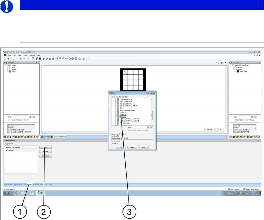
► After defining a JEDEC tray you must assign it to a feeder. Select the relevant SIPLACE JTF feeder
type.
► Select the Feeder tab (1).
► Select Add to add a feeder or Remove to remove a feeder (2).
► Select the relevant SIPLACE JTF feeder(s) (multiple selection is possible) and confirm with OK. As-
signed SIPLACE JTF feeders (3) are displayed in the Assignment window.
4.7.3
4.7.3 Assignment of JEDEC Tray to the Component Shape – Component Shape Tree View
Assignment of JEDEC Tray to the Component Shape – Component Shape Tree View
To be able to place a component with the SIPLACE JTF-S, SIPLACE JTF-M later on, you must assign
a JEDEC tray to the component shape.
NOTICE
JEDEC tray standard
In order to be used in a SIPLACE JTF-S, SIPLACE JTF-M feeder, the dimensions must comply
exactly with the JEDEC tray standard. In the example, a JEDEC tray with the name JEDEC
Test was defined.
Setting up and Commissioning
Configuration of SIPLACE JTF-MW in SIPLACE Pro
38 User Manual JTF-MW on SIPLACE E
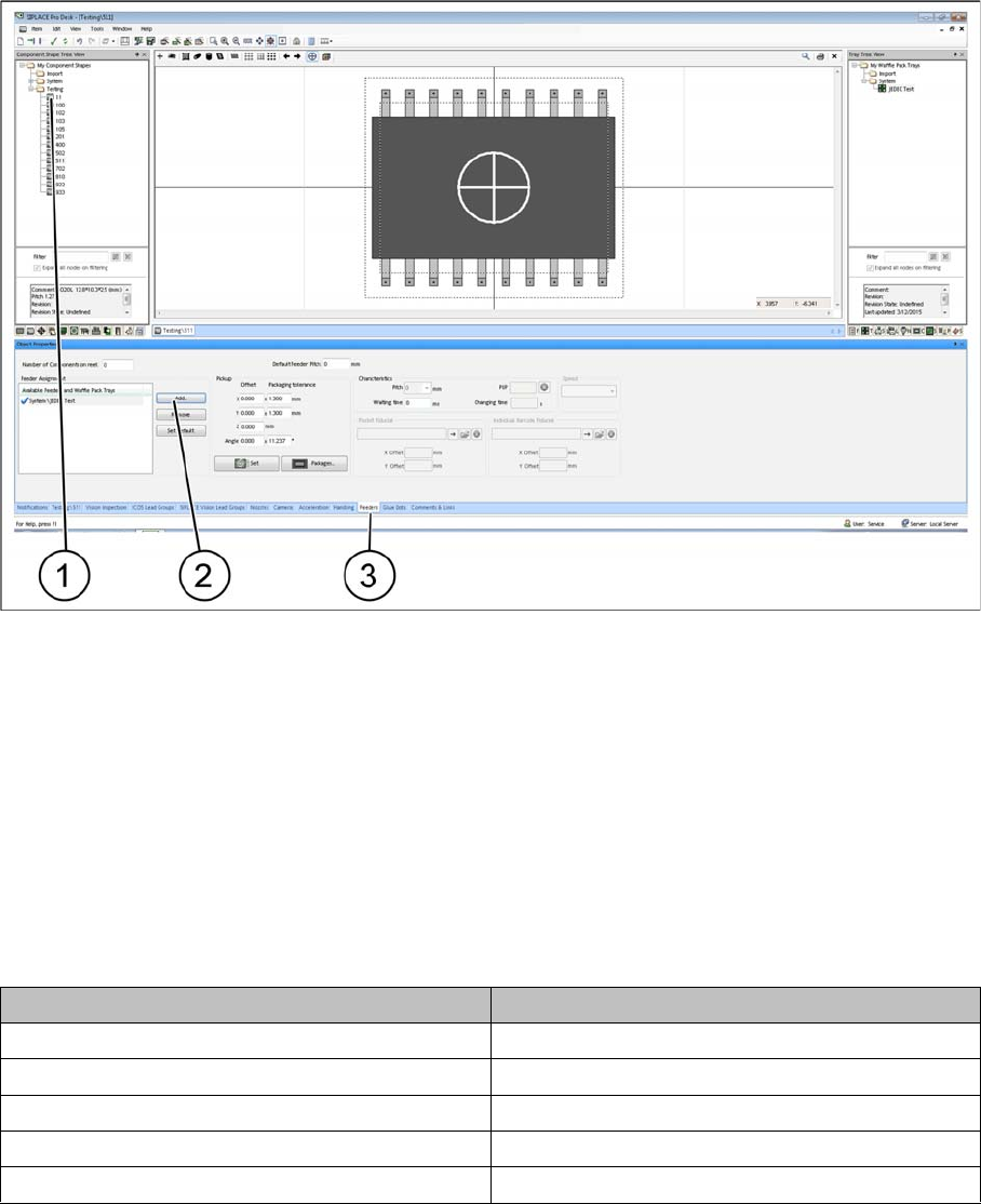
► (1) Select the component shape.
► (3) Select the Feeders tab.
► (2) Select Add to add the JEDEC tray.
► Select an appropriate JEDEC tray from the list. The selected JEDEC tray is displayed under
Assignment.
4.7.4
4.7.4 Configuration of the Setup – Setup Tree View
Configuration of the Setup – Setup Tree View
4.7.4.1
4.7.4.1 Head Configurations for SIPLACE E
Head Configurations for SIPLACE E
The SIPLACE JTF-M can only be set up on location 2.
The following head configurations are possible:
4.7.4.2
4.7.4.2 Table Configuration
Table Configuration
After you have configured one of the heads mentioned in "4.7.4.1 Head Configurations for SIPLACE E"
[ ➙ 38], select the table that is the prerequisite for setting up a JTF-MW.
Head 1 Head 2
SIPLACE CP14 -
SIPLACE CP12
SIPLACE CP12 SIPLACE PP
SIPLACE CP6 SIPLACE PP
- SIPLACE TH
Setting up and Commissioning
Configuration of SIPLACE JTF-MW in SIPLACE Pro
User Manual JTF-MW on SIPLACE E 39
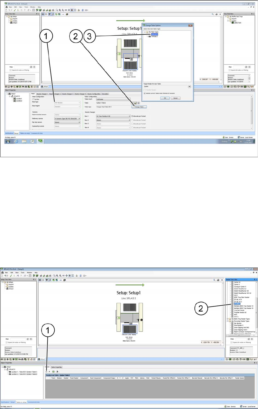
SIPLACE Pro - Example with table configurations
Head configuration: P&P Module (as example) (1)
Table configuration Change Table (2)
Confirm each selected table type (3) and confirm with OK.
After the relevant table type has been selected, the options in the Camera and Nozzle Changer fields
are automatically disabled. For design reasons, these configuration options are no longer available after
the table type has been selected.
All cameras and nozzle changer configurations that are selectable are displayed as active.
4.7.4.3
4.7.4.3 Configuring the SIPLACE JTF-MW on the Table
Configuring the SIPLACE JTF-MW on the Table
There are two ways for setting up the SIPLACE JTF-MW on the table:
Manually dragging the SIPLACE JTF-MW onto the table (2).
By selecting the Insert a new item into the collection menu option (1).