YG300_Mainte_E.pdf - 第43页
3-5 3 Periodic maintenance items 8 C h e c k t h a t t h e o i l w a s r e m o v e d . B l o w a i r t h r o u g h t h e s p l i n e s h a f t a g a i n w h i l e u s i n g c o m m e r c i a l l y - a v a i l a b l e o i…
3-4
3
Periodic maintenance items
2.2 Cleaning and lubricating a nozzle holder
If the nozzle holder spring-action is poor, this adversely affects all operations of component pickup,
recognition and mounting. Periodically (once every two months) clean the nozzle holder with alcohol (IPA or
ethanol) and lubricate it with turbine oil to maintain smooth movement.
e
1
Press the emergency stop button.
The machine must be in emergency stop to
ensure safety during work.
2
Remove the nozzles and immerse
the nozzle holder in alcohol.
Clean the nozzle holder by immersing it in
alcohol as explained below.
1. Place a cloth under the head.
2. Prepare a small container deep enough
to hold the entire nozzle holder. Then
pour this container about 80% full of
alcohol.
3. Lower the head by hand while bringing
the alcohol container up against the
nozzle shaft so the entire nozzle holder is
immersed in alcohol for several seconds.
4. Remove the alcohol container and push
up on the nozzle holder with your finger
several times.
53306-F1-00
3
Immerse the nozzle holder in
alcohol again.
Repeat steps 2 and 3 until the spring-action
becomes smooth.
4
Use air blow to remove foreign
matter.
Insert an air blow gun into the air joint
section and blow air while holding a
cleaning cloth or paper towel against the
lower end of the head.
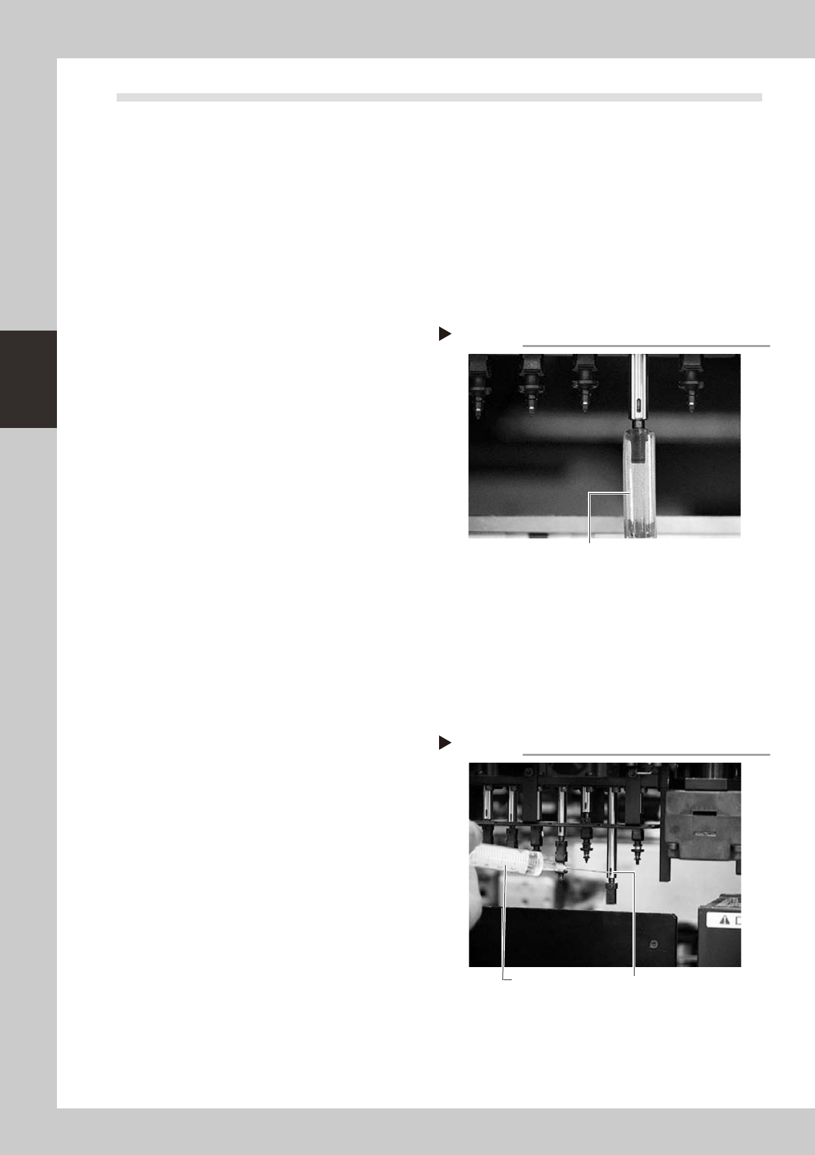
5
Lubricate the slide section and
check the movement.
Apply turbine oil to the buffing section (slide
section) and push up the nozzle holder by
hand several times to check that it moves
up and down smoothly.
53307-F1-00
6
Wipe away excess oil.
Wipe away excess oil with a lint-free
cleaning cloth or paper towel.
7
Blow off excess oil remaining in the
nozzle holder.
As in step 4, insert the air blow gun into the
air joint section and blow air through the
spline shaft while holding a cleaning cloth or
paper towel against the lower end of the
head.
Cleaning the nozzle holder
Step 2
Container holding alcohol
Lubricating the nozzle holder
Step 5
Lubricate here.
Nozzle holder
lubricating syringe

3-5
3
Periodic maintenance items
8
Check that the oil was removed.
Blow air through the spline shaft again while
using commercially-available oil blotting
paper, and check for residual oil in the
nozzle holder.
53308-F1-00
n
NOTE
Performing step 7 is usually sufficient to remove residual
oil. However, if oil still remains then blow air once again.
9
Reinstall the nozzle.
Reinstall the nozzle back onto the head or
the nozzle station (option).
Step 8
Checking for residual oil
Oil blotting paper
Oil may appear after blowing air.
Repeat the air blow until oil no longer
appears.
3-6
3
Periodic maintenance items
2.3 Cleaning and greasing the X-axis
To clean and grease the X-axis ball screws and linear guides, follow the steps below. Prepare a grease gun and
the specified grease (NSL).
c
CAUTION
When handling grease or lubricant, read and follow the precautions listed in section 2.2.2, "Lubricating tools and
grease", in Chapter 1.
2.3.1 Cleaning and greasing the X-axis ball screws
e
1
Press the emergency stop button.
The machine must be in emergency stop to ensure safety during work.
2
Remove the X-axis ball screw cover.
1. Use a Phillips screwdriver to remove the
four screws securing the cover.
2. When removing the cover for table A or D,
move the head to the left end and
remove the cover by pulling it to the
right. When removing the cover for table
B or C, move the head to the right end
and remove the cover by pulling it to the
left.
53309-F1-00
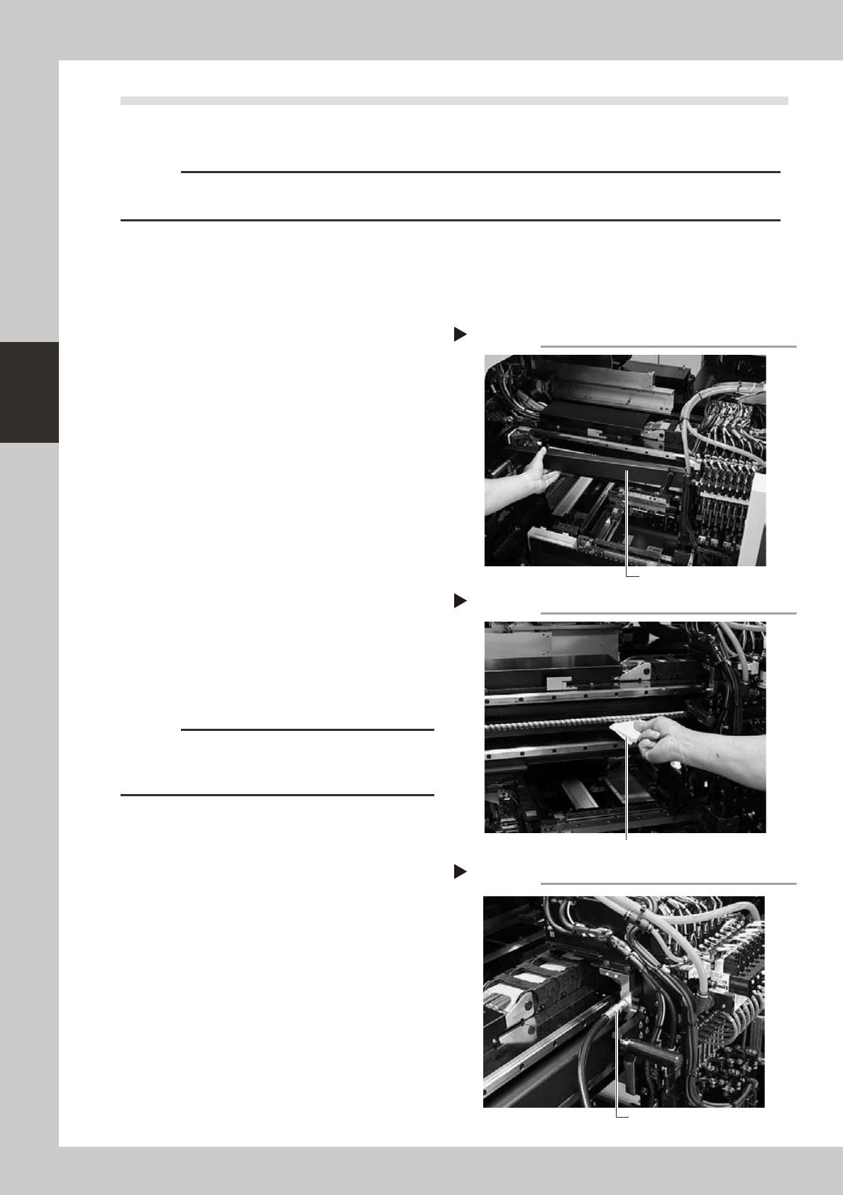
3
Clean the X-axis ball screw.
1. Using the handles, move the head to one
end of the X-axis.
2. Wipe away the old grease and dirt from
the ball screw with a lint-free cloth or
paper towel (for clean room use).
3. Move the head to the opposite end of
the X-axis and wipe the ball screw clean.
53310-F1-00
c
CAUTION
Wipe away the old grease and dirt in the lead groove
of the ball screw. Also check that no debris or residue
remains in the lead groove.
4
Apply new grease to the ball screw.
Use the grease gun to supply the specified
grease (NSL) to the grease nipple located in
the following position.
• Tables A and D: Upper left of head unit
• Tables B and C: Upper right of head unit
53311-F1-00
Removing the X-axis ball screw cover
Step 2
X-axis ball screw cover
Cleaning the X-axis ball screw
Step 3
Wipe with cleaning cloth or paper towel
Greasing the X-axis ball screw
Step 4
Grease gun