YG300_Mainte_E.pdf - 第69页
4-4 4 How to replace consumable parts 4 . R e p l a c i n g t h e f e e d e r v a l v e s 1 T u r n o f f t h e m a c h i n e p o w e r s w i t c h . Q u i t t h e a p p l i c a t i o n s o f t w a r e ( V G O S ) a n d …
4-3
4
How to replace consumable parts
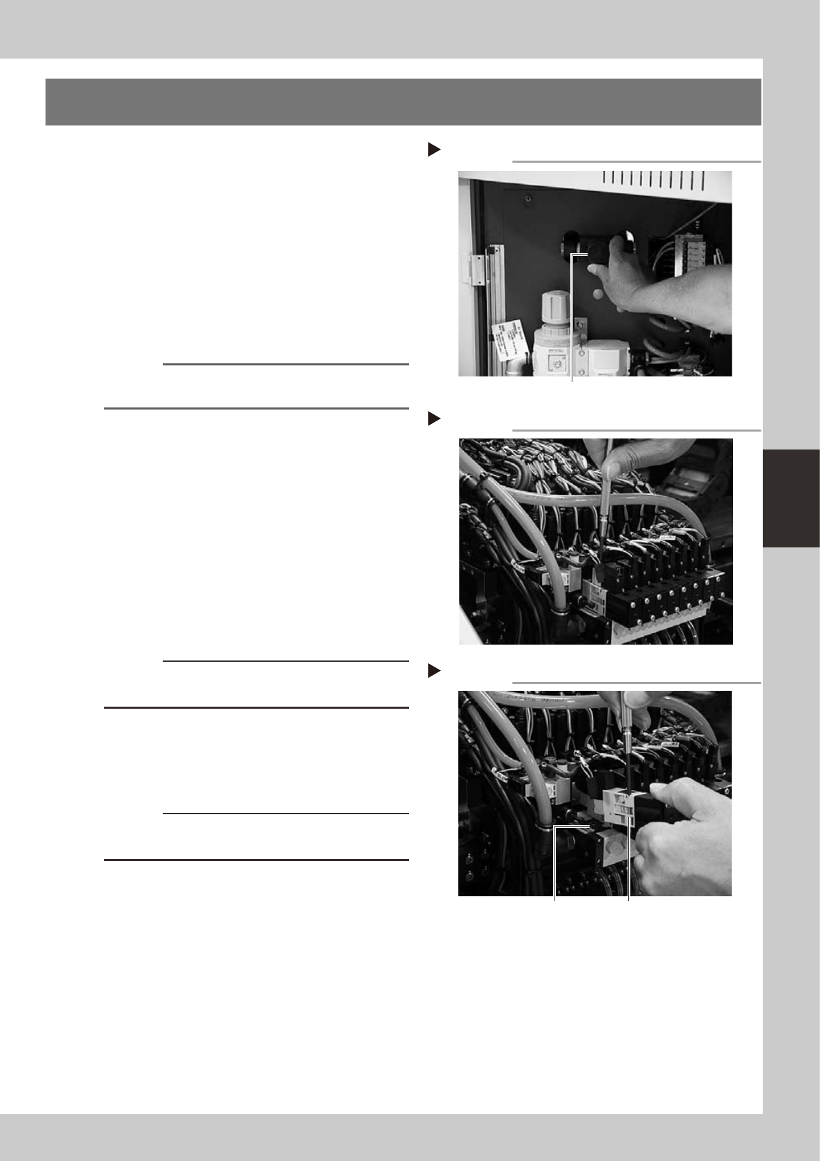
3. Replacing the ejector valves
1
Shut off the air supply and turn off
the machine.
Turn the air supply/shutoff switch (located
behind the lower left panel) to the right to
cut off the air supply, quit the application
software (VGOS), and turn off the machine
power switch.
53404-F1-00
2
Unplug the blow valve connector.
Unplug the connector of the blow valve
attached to the ejector valve to be
replaced.
Reference
To replace an ejector valve, the blow valve attached
to that ejector valve must first be removed.
3
Remove the blow valve.
Use the precision Phillips screwdriver to
loosen the two screws securing the blow
valve and then remove the blow valve. You
will see the two screws securing the ejector
valve.
53405-F1-00
4
Remove the ejector valve.
Use the precision Phillips screwdriver to
loosen the two screws securing the ejector
valve and remove the ejector valve.
53406-F1-00
c
CAUTION
Be careful not to drop the gasket fitted to the backside
of the ejector valve.
5
Attach a new ejector valve.
Use the precision Phillips screwdriver to
tighten the two screws to secure the new
ejector valve.
c
CAUTION
Do not forget to fit the gasket in place. Use caution not
to fit the gasket inside-out or to pinch it.
6
Reassemble the valve unit in the
reverse order of the above
procedure.
Reconnect the air hoses and connectors
back to their original positions.
7
Check the operation.
After reassembling the valve unit, supply air
to the machine and turn on the machine
power switch. Then check that the vacuum
levels are normal, using the procedure
described in step 5 of section 3.2.2,
”Lubricating the slide section and checking
the negative pressure", in Chapter 3.
Shutting off the air supply
Step 1
Air supply/shutoff switch
Removing the blow valve
Step 3
Removing the ejector valve
Step 4
Ejector valve
Gasket
4-4
4
How to replace consumable parts
4. Replacing the feeder valves
1
Turn off the machine power switch.
Quit the application software (VGOS) and
turn off the machine power switch by turning
it to the left.
2
Shut off the air supply.
Open the lower left cover on the front of the
machine and turn the air supply/shutoff
switch to the right to cut off the air supply.
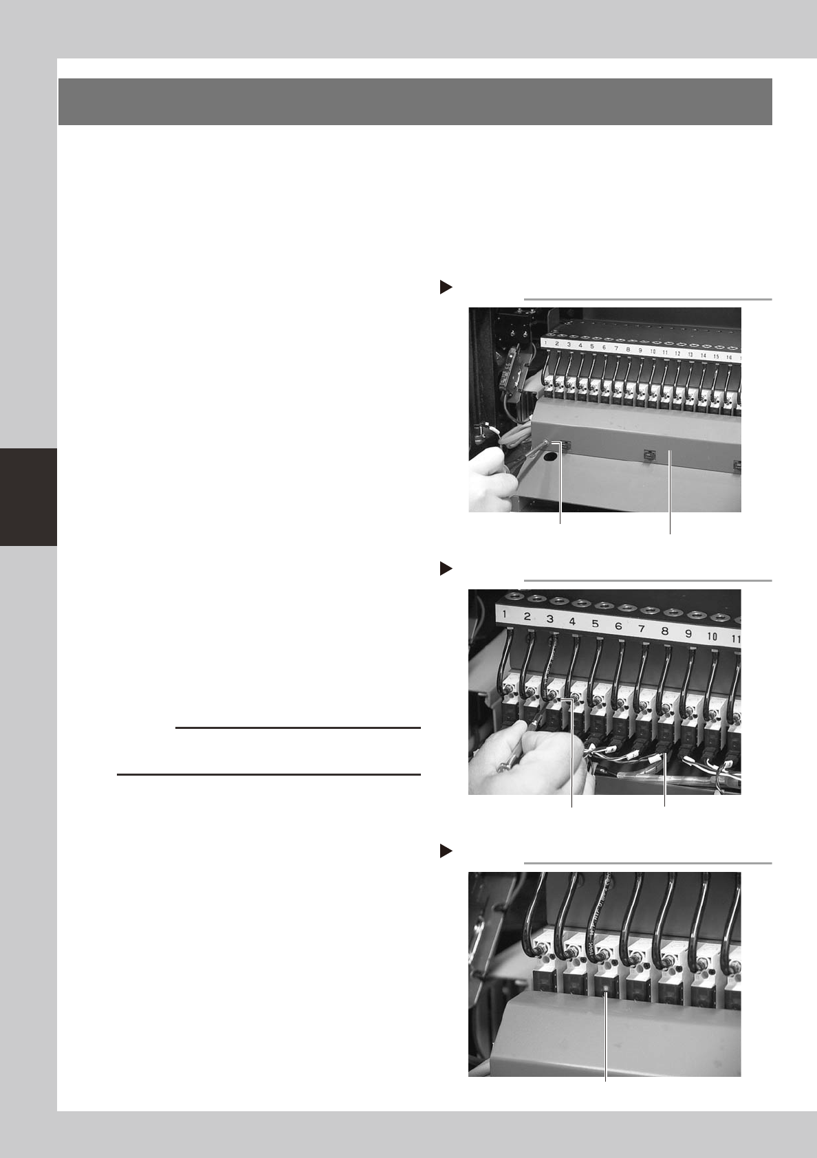
3
Remove the wire harness cover.
Use a Phillips screwdriver to loosen and
remove the screws that secure the wire
harness cover to the machine body.
53407-F1-00
4
Remove the feeder valve.
1. Detach the connector from the feeder
valve to be replaced.
2. Use a precision screwdriver to loosen the
two screws and remove the feeder valve.
53408-F1-00
5
Remove the air hose.
Remove the air hose for the feeder valve to
be replaced. Cutting the air hose makes it
easier to remove the air hose.
(New air hoses are included in the feeder
valve kit that comes with the machine.)
6
Attach a new feeder valve and the
wire harness cover.
Install the new feeder valve and wire
harness cover in the reverse order of steps 3
and 4.
c
CAUTION
Do not forget to fit the gasket in place. Use caution not
to fit the gasket inside-out or to pinch it.
7
Connect an air hose.
Connect a new air hose to the new feeder
valve.
8
Check the ejector operation.
1. Supply air to the machine and turn on
the machine power switch.
2. Install a feeder at the new feeder valve
position.
3. Open the [Unit]-[Feeder] tab screen and
turn the feeder on and off, to check the
feeder valve and LED operations.
53409-F1-00
Removing the wire harness cover
Step 3
Wire harness cover
Remove the screws
at both ends.
Removing the feeder valve
Step 4
Valve connector
Loosen these
two screws.
Checking the feeder valve operation
Step 8
LED lamp
4-5
4
How to replace consumable parts
5. Replacing the blow station filters
To replace the blow station filters, follow the steps below.
A blow station small filter is located under the blow station for each table.
Blow station large filters are installed in 2 locations: inside the front left cover and inside the rear right cover.
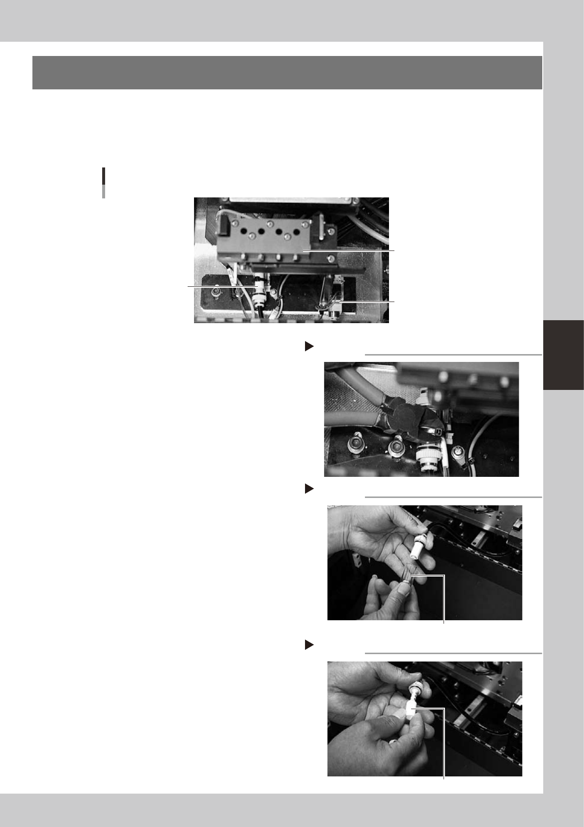
n
Blow station filter (small)
Blow station
Blow station
Filter unit
(blow station small filter)
Blow station valve
53413-F1-00
1
Cut off the cable tie.
Cut off the cable tie securing the filter unit.
53414-F1-00
2
Disconnect the air hose.
Disconnect the air hose on the valve side.
3
Remove the filter cover.
Rotate the filter cap through 90° and
remove the filter cover.
53415-F1-00
4
Replace the filter.
Replace the dirty filter with a new one.
53416-F1-00
5
Install the filter.
Install the filter in the reverse order of the
removal procedure.
Cutting off the cable tie
Step 1
Removing the filter cover
Step 3
Filter cover
Replacing the filter
Step 4
Filter