YG300_Mainte_E.pdf - 第47页
3-9 3 Periodic maintenance items 2 . 4 C l e a n i n g a n d g r e a s i n g t h e Y - a x i s T o c l e a n a n d g r e a s e t h e Y - a x i s b a l l s c r e w s a n d l i n e a r g u i d e s , f o l l o w t h e s t e…
3-8
3
Periodic maintenance items
2.3.2 Cleaning and greasing the X-axis linear guides
e
1
Press the emergency stop button.
The machine must be in emergency stop to
ensure safety during work.
2
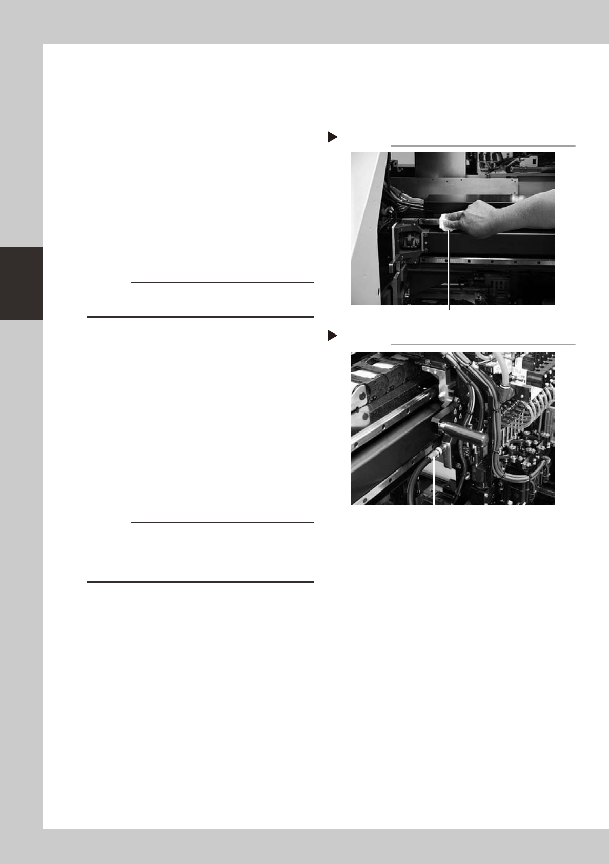
Clean the X-axis linear guides.
1. Move the head to one end of the X-axis,
and wipe away the old grease and dirt
from the linear guides with a lint-free
cloth or paper towel (for clean room
use).
2. Move the head to the opposite end of
the X-axis and wipe the linear guides
clean.
53313-F1-00
c
CAUTION
Wipe away the old grease and dirt in the grooves of the
linear guide rails.
3
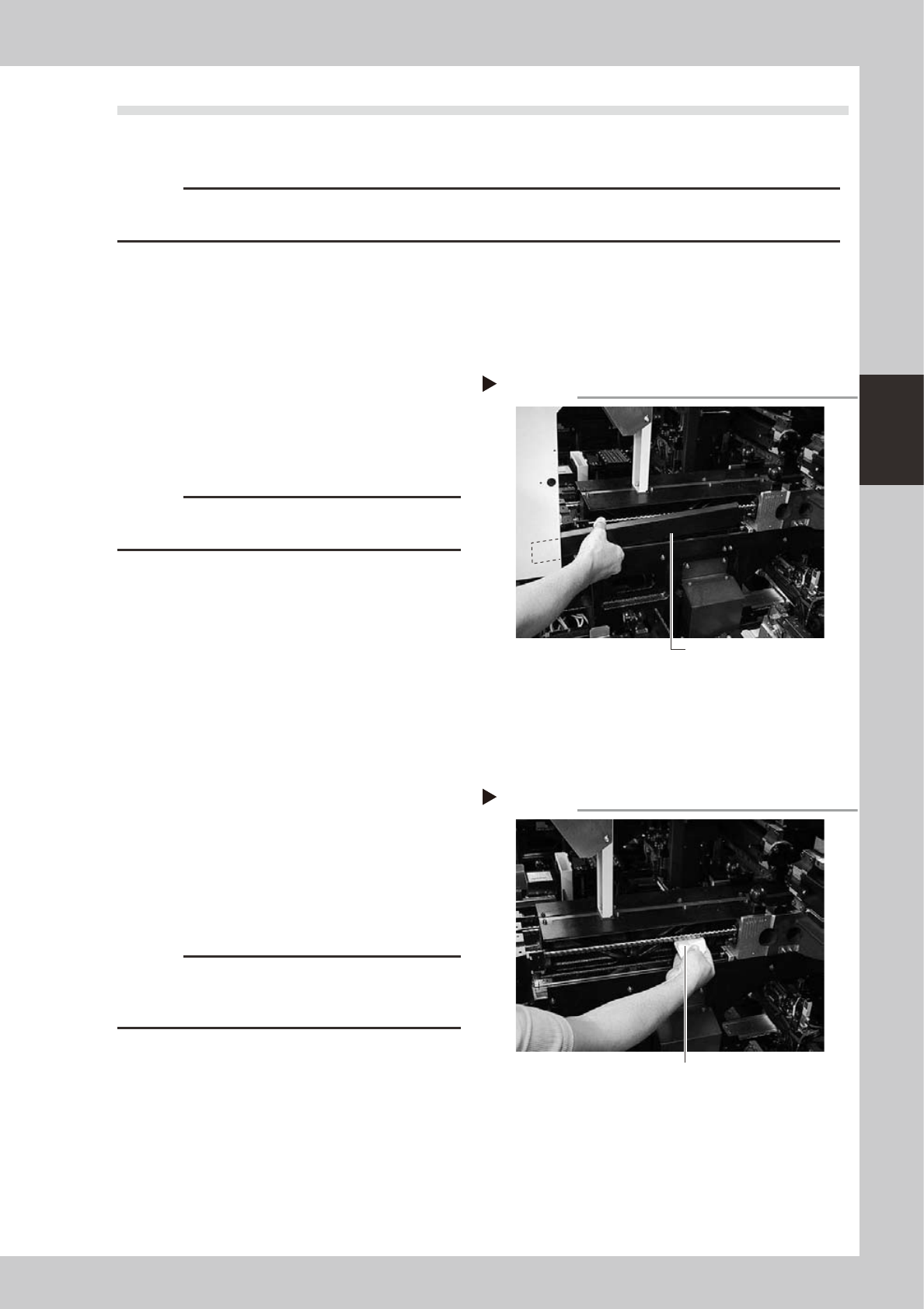
Apply new grease to the linear
guides.
Use the grease gun to supply the specified
grease (NSL) to the grease nipples. Two
nipples are vertically located in the following
position.
• Tables A and D: Right side of head unit
• Tables B and C: Left side of head unit
53314-F1-00
4
Remove excess grease.
After moving the head back and forth a few
times along the X-axis, wipe away excess
grease.
c
CAUTION
Repeat the above steps until finally there are no longer
any grease deposits. If production starts with grease
deposits still remaining, this might cause grease to
spatter and badly affect the production yield.
Cleaning the X-axis linear guides
Step 2
Wipe with cleaning cloth or paper towel
Greasing the X-axis linear guides
Step 3
Grease gun
3-9
3
Periodic maintenance items
2.4 Cleaning and greasing the Y-axis
To clean and grease the Y-axis ball screws and linear guides, follow the steps below. Prepare a grease gun and
the specified grease (NSL).
c
CAUTION
When handling grease or lubricant, read and follow the precautions listed in section 2.2.2, "Lubricating tools and
grease", in Chapter 1.
2.4.1 Cleaning and greasing the Y-axis ball screws
e
1
Press the emergency stop button.
The machine must be in emergency stop to
ensure safety during work.
2
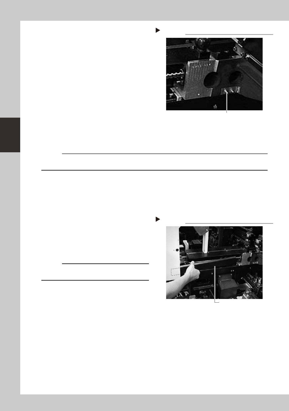
Remove the Y-axis covers.
1. Move the X-axis beam to the front side of
the machine (toward you) and remove
the two screws securing the rear side
(inner section) of each Y-axis cover.
c
CAUTION
Be careful not to drop the screws that secure the
covers.
2. Move the X-axis beam all the way to the
rear side (inner side) and remove the two
screws securing the front side (outer
section) of each Y-axis ball screw cover.
3. To remove each Y-axis ball screw cover,
first pull the cover to the front side (outer
side) of the machine so that the inner
end of the cover comes out of the X-axis
frame. Then move the cover back to the
rear side (inner side) and remove it.
53315-F1-00
3
Clean the Y-axis ball screws.
1. Wipe away the old grease and dirt from
the ball screws with a lint-free cloth or
paper towel (for clean room use).
2. Move the X-axis beam to the opposite
side and wipe the ball screws clean.
53316-F1-00
c
CAUTION
Wipe away the old grease and dirt in the lead groove
of each ball screw. Also check that no debris or residue
remains in the lead groove.
Removing the Y-axis cover
Step 2
Y-axis cover
Cleaning the Y-axis ball screw
Step 3
Wipe with cleaning cloth or paper towel.
3-10
3
Periodic maintenance items
4
Apply new grease to the ball
screws.
Use the grease gun to supply the specified
grease (NSL) to the grease nipple (grease
nipple closer to the outer side) for each
Y-axis ball screw.
53347-F1-00
5
Remove excess grease.
1. Using the handles, move the X-axis beam
back and forth a few times along the
Y-axis to spread grease over the entire
ball screw.
2. Wipe away excess grease from the ball
screws and the nut edges (outer and
inner sides).
6
Reattach the Y-axis covers.
Attach the covers in the reverse order of the
removal procedure in step 2.
c
CAUTION
Be sure to reattach the covers back to their original positions. If production starts without reattaching the covers,
spattering grease might badly affect the production yield.
2.4.2 Cleaning and greasing the Y-axis linear guides
e
1
Press the emergency stop button.
The machine must be in emergency stop to
ensure safety during work.
2
Clean the Y-axis linear guides.
1. Move the X-axis beam to the front side of
the machine (toward you), and remove
the two screws securing the rear side
(inner section) of each Y-axis cover.
53315-F1-00
c
CAUTION
Be careful not to drop the screws that secure the
covers.
2. Move the X-axis beam all the way to the
rear side (inner side) of the machine and
remove the two screws securing the front
side (outer section) of each Y-axis cover.
3. To remove each Y-axis cover, first pull the
cover to the front side (outer side) of the
machine so that the inner end of the
cover comes out of the X-axis frame.
Then move the cover back to the rear
side (inner side) and remove it.
Removing the Y-axis cover
Step 2
Y-axis cover
Grease nipple for Y-axis ball screw
Grease nipple for Y-axis ball screw
Step 4