DR_A_MANUAL.pdf - 第3页
Connection Desoldering Iron R ef. DR 5 6 0 -A Tip Re f . C5 60003 to desolder ing mo dule to stand Suction Filter R e f . 0 8 218 3 0 Supplied with desoldering module Desoldering process Use a ti p with a l arge r dia me…
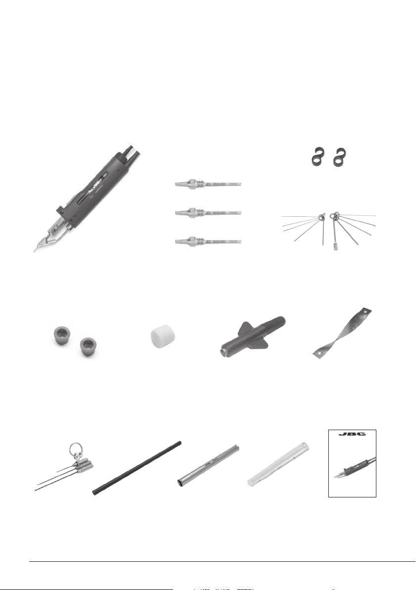
Packing List
Ref. DR560
Desoldering Iron
Tips ................................. 3 units
Ref. C560005* (x1)
Ref. C560013* (x1)
Ref. C560004* (x1)
Desoldering Iron .......... 1 unit
Ref. DR560-A
C560003 already inserted
The following items should be included:
Union flanges .......... 1 unidad
Ref. 0 0113 5 6
Tip cleaning set ............ 1 unit
Ref. 0965970*
Internal gasket .... 1 u.
Ref. 0019208*
It contains 2 gaskets
Filter box .............. 1 u.
Ref. 0780840
It contains 10 filters
Spanner ............. 1 unit
Ref. 0780550*
Spiral Filter .......... 1 u.
Ref. 0812330*
Long tip cleaning
set .................. 1 u.
Ref. 0965760*
Cleaning
stick .............. 1 u.
Ref. 0786640
Metal Solder
Collector .... 1 u.
Ref. 0812630*
Glass Solder
Collector ..... 1 u.
Ref. 0812620*
Manual ......... 1 u.
Ref. 0008867
*DR560-A Desoldering Iron accessories included in the Ref. 0010261
2
www.jbctools.com
Connection
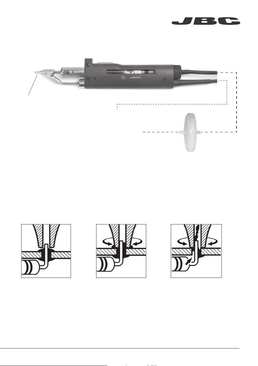
Desoldering Iron
Ref. DR560-A
Tip
Ref. C560003
to desoldering module
to stand
Suction Filter
Ref. 0821830
Supplied with desoldering module
Desoldering process
Use a tip with a larger diameter than the pad to achieve maximum aspiration and thermal efficiency.
Place the tip with the
component terminal in
the hole.
After pressing the desoldering key there is a slight delay until the self-contained vacuum pump
stops. This makes sure that the vacuum circuit is completely empty. If any solder remains are left
on a terminal after desoldering it, resolder it with fresh solder and repeat the desoldering operation.
When the solder liquefies,
gently rotate the tip so
that the compo nent
terminal can be lifted off.
Press the vacuum pump
button long enough to
remove the solder.
3. Aspirating1. Placing 2. Rotating
www.jbctools.com
3
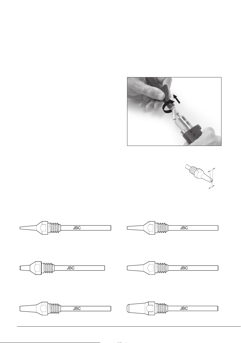
A ø
B ø
C560-001
C560-002
C560-003
C560-004
C560-009
C560-014
Changing Tips
This operation should be done while the tip is hot and at a minimum temperature of 250°C, so that
any tin left inside is still molten.
1. Removing
Use the special spanner to unscrew the tip.
2. Inserting
Fit the new tip and tighten with the spanner
to make sure it is air tight.
Compatible Tips
The DR560 uses C560 tips.
Find the model that best suits your soldering needs in www.jbctools.com
Here are some C560 tips in real size:
250ºC minimum
C560-001 A=1,4 B=0,6 max. pin=0,4 mm
(A=0.05 B= 0.02 max. pin= 0.01 in)
C560-002 A=1,8 B=0,8 max. pin=0,6 mm
(A=0.07 B= 0.03 max. pin= 0.02 in)
C560-003 A=2,7 B=1 max. pin=0,8 mm
(A=0.1 B= 0.04 max. pin= 0.03 in)
C560-004 A=3,2 B=1,3 max. pin=1,1 mm
(A=0.12 B= 0.05 max. pin= 0.04 in)
C560-009 A=5 B=1,3 max. pin=1,1 mm
(A=0.19 B= 0.05 max. pin= 0.04 in)
C560-014 A=2,5 B=0,8 max. pin=0,6 mm
(A=0.09 B= 0.03 max. pin= 0.02 in)
4