TR7500E_Manual_en_v28.pdf - 第7页
T a b l e o f C on t e n ts T R 7500 U S E R M A N U AL VI A P P E ND I X 1 L I GH TI N G C O M P E N S A T I O N ... . ... . .... . ... . .... . ... . .... . ... . .... . .... . ... . . . 2 82

Table of Contents
TR7500 USER MANUAL
V
6.6. Tool................................................................................................................................256
6.7. Switch FOV....................................................................................................................257
6.8. Merge.............................................................................................................................258
6.9. Histogram......................................................................................................................258
6.10. Change Lighting...........................................................................................................259
6.11. Train/ Untrain/ Test/ Untest...........................................................................................261
6.12. Image Library...............................................................................................................261
6.13. Find FOV by Type/Name...............................................................................................264
6.14. Change FOV.................................................................................................................264
6.15. Weighting......................................................................................................................265
CHAPTER 5 INSPECTION DIALOG FUNCTION..........................................266
1. IMAGE DIAGRAM FUNCTION.....................................................................................................266
1.1. Panel Defect Map...........................................................................................................267
1.2. Result Dialog..................................................................................................................267
CHAPTER 6 AUTO CONVEYER WIDTH........................................................272
1. HARDWARE.............................................................................................................................272
2. SOFTWARE SETTING................................................................................................................272
3. SAVING WIDTH DATA TO PROJECT............................................................................................272
4. WIDTH LOADING ....................................................................................................................272
CHAPTER 7 START TO INSPECTION............................................................274
1. POWER ON..............................................................................................................................274
2. OPEN PROGRAM ......................................................................................................................275
3. CHECK BARCODE....................................................................................................................276
4. LINK TO REPAIR STATION.........................................................................................................277
5. INSPECT ON ANOTHER MACHINE .............................................................................................277
6. STOP TESTING AND SHUT DOWN ...............................................................................................277
CHAPTER 8 OFFLINE EDITOR.......................................................................279
1. SOFTWARE..............................................................................................................................279
2. SETTING.................................................................................................................................279
3. PROCEDURE............................................................................................................................279
3.1. Editing component library..............................................................................................279
3.2. Train Dialog...................................................................................................................280
4. AUTO FEEDBACK FUNCTION....................................................................................................280
4.1. Objective........................................................................................................................280
4.2. Setting............................................................................................................................280
4.3. Operation Instruction......................................................................................................281

Table of Contents
TR7500 USER MANUAL
VI
APPENDIX 1 LIGHTING COMPENSATION...................................................282
Chapter 1 AOI Standard Project Creation
TR7500 USER MANUAL
1
Chapter 1 AOI Standard Project Creation
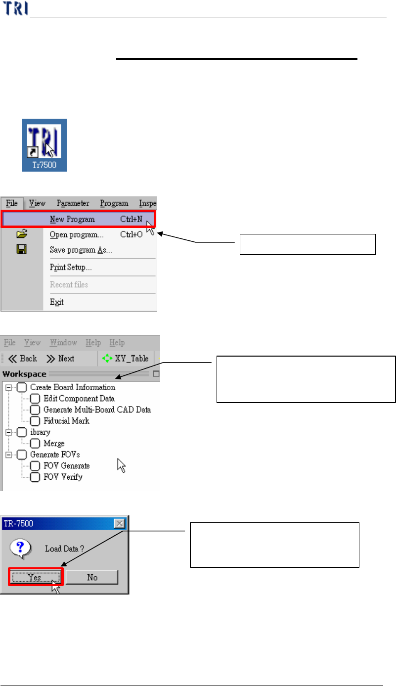
1. Project creation & Start with ATPG
(1) Double click on the shortcut of TR7500E main program.
(2) Create a new project file.
(3) ATPG step is appeared.
(4) Confirm loading CAD file dialog window.
2. Create Board information
For a new program you should create an AOI file (*.aoi) first for TR7500E to
read. There are two types of converters built inside, FABMaster and Default. If there
Create a new project file
Loading CAD file for Translator
(ATPG process)
From Top to Bottom (step by step)
creating a new project file in ATPG