TR7500E_Manual_en_v28.pdf - 第86页
C h a p t e r 2 M a nu a l B a r i n t r o d u ce T R 7500 U S E R M A N U AL 79 4 . 5 . A dd F O V l I t i s on l y e n a b l e d i n t r a i n d i a l o g . l W h e n y o u e l e c t [ A d d F O V ] , i t wil l s h o w…
Chapter 2 Manual Bar introduce
TR7500 USER MANUAL
78
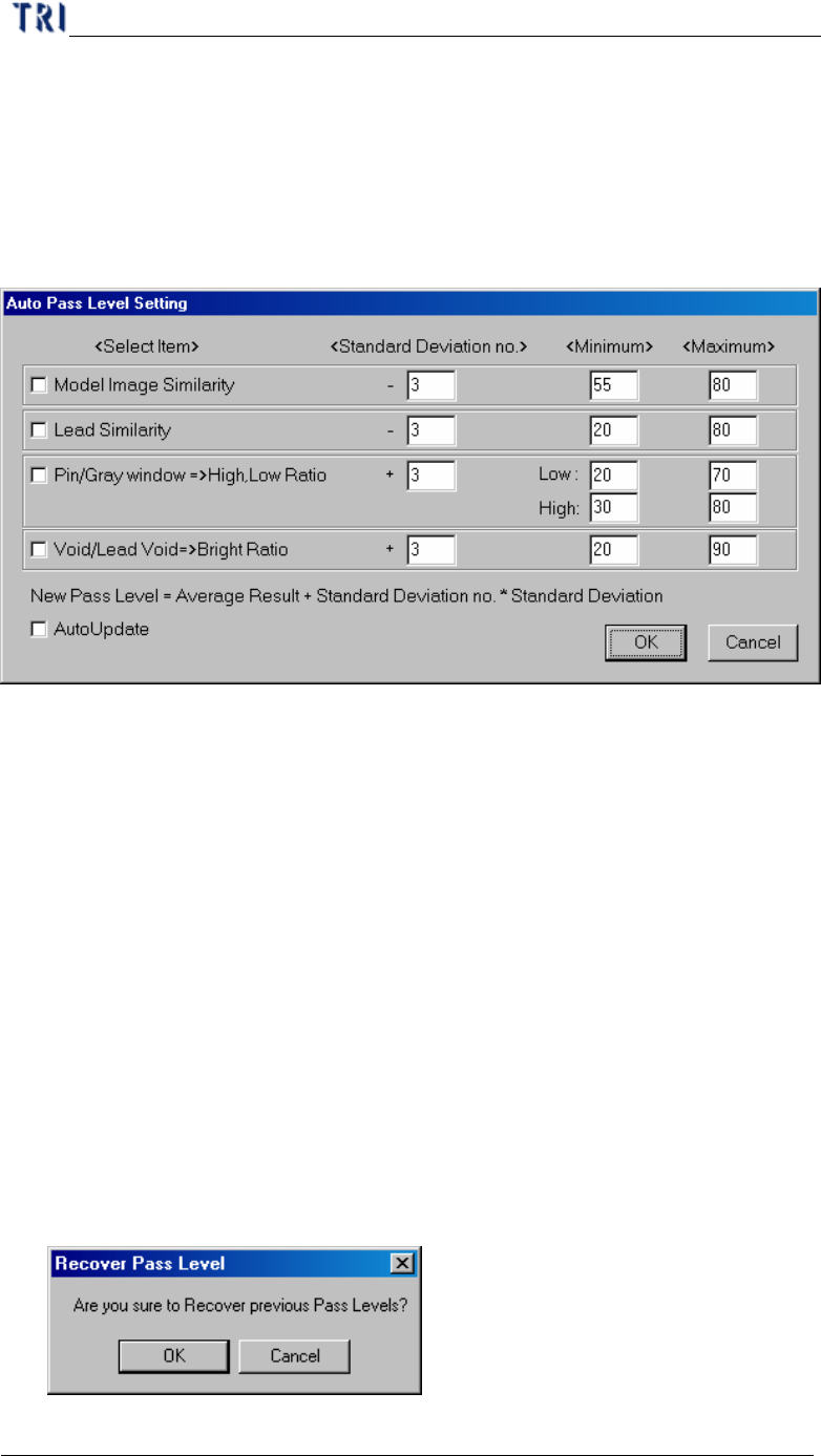
4.4.2. Auto Set Pass Level
l The system will recalculate the new pass level according to the 30 data and the
setting here. You should select the inspection boxes and input [Standard
Deviation no.], [Minimum] and [Maximum] then press [Ok] to change the pass
level.
u Select Item – Select the inspection boxes you want to change.
u Standard Deviation no. – Set a multiple of standard deviation to calculate
parameters. New pass level = Average Result +Standard Deviation no.*
Standard Deviation. The [Average Result] and [Standard Deviation] is
calculated from 30 times results.
u Minimum, Maximum – Give new parameter a range in order not to create
an unsuitable value. If the calculated parameter is smaller than [Min.] value
the system will modify the parameter as [Min.] value; if the calculated
parameter is bigger than [Max.] value the system will modify the parameter
as [Max.] value.
u Auto Update – It means when the total inspection number of times is over
30, the parameter will be calculated after every inspection.
4.4.3. Recover Pass Level
l Press to recover the one former pass level setting.
Chapter 2 Manual Bar introduce
TR7500 USER MANUAL
79
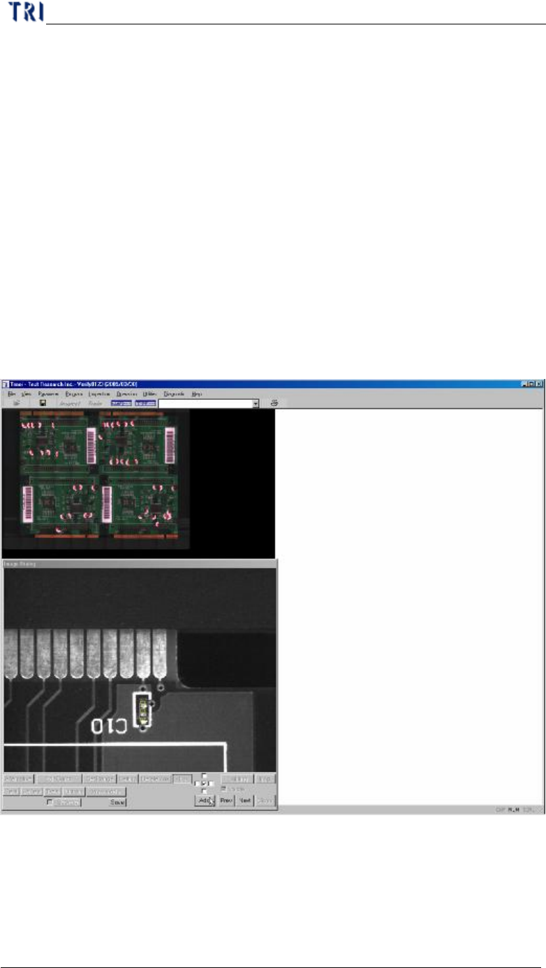
4.5. Add FOV
l It is only enabled in train dialog.
l When you elect [Add FOV], it will show panel map and real time FOV image.
There are two ways to add FOV.
n You can click on the position where you want to add an FOV on panel map
and the camera will move to the position to grab image. Confirm the image
then press [Add]. If it’s multi-board module the system will create FOV to
the relative position. The existing FOV can’t be selected.
n Click the around position on panel map. You can press [Prev.] or [Next] to
find the FOV you want to add. If it’s multi-board module the system will
create FOV to the relative position. The existing FOV can’t be shown.
l You can press [Save] to save the current image in the folder which the project
saves in.
l Add FOV Steps:
Step1. Press [Program/Add FOV]
Step2. Select objective FOV then press [Add]
Step3. You can add other FOVs
Step4. After you finish add FOVs press [Program/Add FOV] again.
Chapter 2 Manual Bar introduce
TR7500 USER MANUAL
80
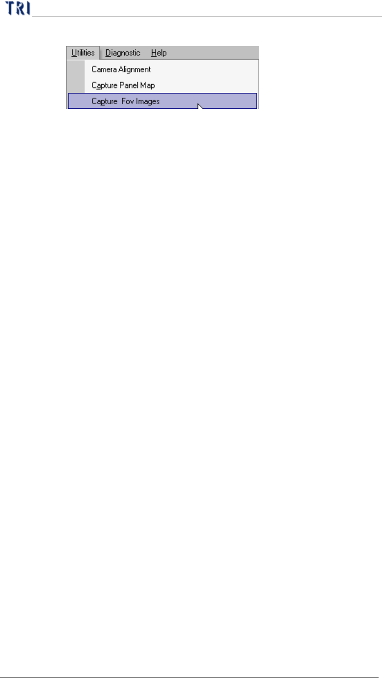
Step5. Close [Train] dialog then press [Utilities/Capture FOV Images].
Step6. Reopen train dialog to edit the new FOV.
4.6. Delete FOV
l It is only enabled in train dialog.
l When you elect [Delete FOV], it will show panel map and real time FOV image.
There are two ways to delete FOV.
n You can click on the position where you want to delete FOV on panel map
and the camera will move to the position to grab image. Confirm the image
then press [Delete]. If it’s multi-board module the system will delete FOV to
the relative position.
n Click the around position on panel map. You can press [Prev.] or [Next] to
find the FOV you want to delete. If it’s multi-board module the system will
delete FOV to the relative position.
l Delete FOV Steps:
Step1. Press [Program/Delete FOV]
Step2. Select objective FOV then press [Del]
Step3. You can delete other FOVs
Step4. After you finish delete FOVs press [Program/Delete FOV] again.
Step5. Close [Train] dialog then press [Utilities/Capture FOV Images].
4.7. Non CAD
4.7.1. Objective
When the user doesn’t have the CAD data to inspect, this function can get the position
of components the CAD coordinate by handle.
4.7.2. Start Up
Select [Program/Non CAD/Teach]