Nordson_EFD_RV_Series_Operating_Manual.pdf - 第128页
RV Series Automated Dispensing Systems 128 www.nordsonefd.com info@nordsonefd.com +1-401-431-7000 Sales and service of Nordson EFD dispensing systems are available worldwide. Setting DXF Import Pr eferences Click the OPT…
RV Series Automated Dispensing Systems
127www.nordsonefd.com info@nordsonefd.com +1-401-431-7000 Sales and service of Nordson EFD dispensing systems are available worldwide.
AppendixC, DXF File Import
This appendix provides an overview of the DXF screen components and the procedure for importing DXF files.
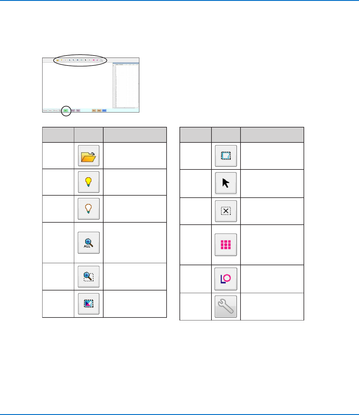
Overview of the DXF Screen
Icon
Name
Icon Function
Open a
File
Opens a file
Show All
Layers
Shows all layers of the
open DXF file
Hide All
Layers
Hides all layers of the
open DXF file
See All
Compresses or resizes
the display so that all
points of the open DXF
file are displayed in
the viewing area of the
screen
Zoom
Zooms to the selected
area
Select All
Selects all the points in
the DXF file
Icon
Name
Icon Function
Select
Selects only the points
within the area of the
rectangle
Select
Directly
Selects one element
Cancel
Select
Cancels any selections
Point
Dispense
Inserts Dispense Dot
commands for all the
selected points on an
imported DXF image
Line
Dispense
Inserts line dispense
commands for all the
selected shapes on an
imported DXF image
Option
Refer to “Setting DXF
Import Preferences” on
page128.
RV Series Automated Dispensing Systems
128 www.nordsonefd.com info@nordsonefd.com +1-401-431-7000 Sales and service of Nordson EFD dispensing systems are available worldwide.
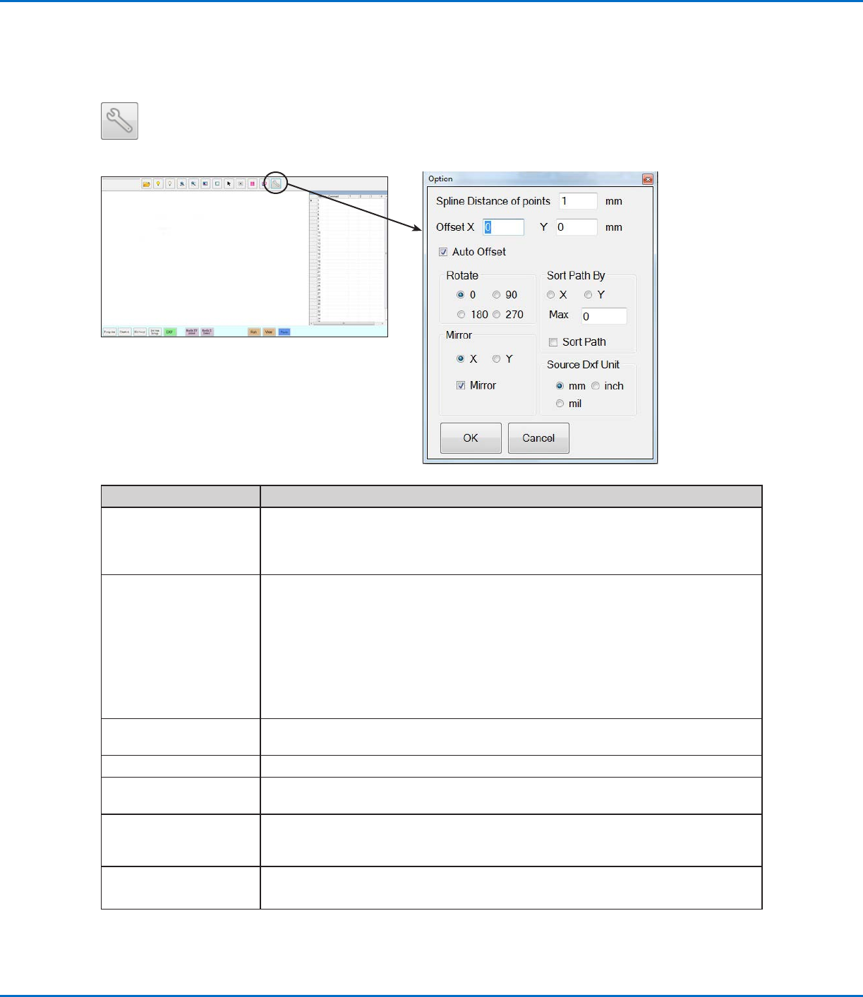
Setting DXF Import Preferences
Click the OPTION icon on the DXF screen to set DXF import preferences.
AppendixC, DXF File Import (continued)
Item Description
Spline Distance of points
(mm)
Specifies the distance between any two points on a curve when the curve is
converted to coordinates. For example, when this value is set to 1 and a 10-mm long
curve is converted to commands, the result will be a series of Line Start, Line Passing,
and Line End commands that will produce a curve with a total of 11 points.
Offset X, Y After you create program commands using Point Dispense or Line Dispense, the
resulting XY values may be negative numbers. This causes the imported points to
display off the grid when viewed on the Secondary View screen. To resolve this
issue, enter X and / or Y values in the offset fields of the Option window such that the
imported XY values change to positive values. For example, if an imported XY value is
-150, -150, 0, then enter 200 for Offset X and 200 for offset Y, click OK, and then click
the Point Dispense or Line Dispense icon again to refresh the values. The new values
will be 50, 50, 0 and the points will be visible on the Secondary View screen grid when
you go to the Program screen.
Auto Offset When selected, causes the system to align all the points in the middle of the fixture
plate to the greatest extent possible.
Rotate Rotates the file by the specified degrees
Mirror Mirrors the file over the X or Y axis, as selected. Select the Mirror checkbox for the
option to take effect when the file imports.
Sort Path By For arrays of dispense dots, sorts the resulting Dispense Dot commands by the X or Y
coordinates, as specified. Refer to “Using the Sort Path By Option” on page132 for
details about this option.
Source Dxf Unit Toggles the display of units between millimeters, inches, and mils
NOTE: A mil is one-thousandth of an inch, or 0.001 inch.
RV Series Automated Dispensing Systems
129www.nordsonefd.com info@nordsonefd.com +1-401-431-7000 Sales and service of Nordson EFD dispensing systems are available worldwide.
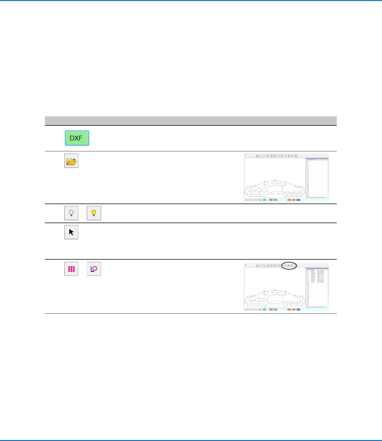
Importing a DXF File
PREREQUISITES
The system is properly set up. Refer to “Setting Up and Calibrating the System (Required)” on page45.
If the tip or any element of the Zaxis head was changed, repeat system setup and calibration using the Robot
Initial Setup wizard. Refer to “Setting Up the System Using the Robot Initial Setup Wizard” on page48.
The system is in the correct mode (Tip or CCD).
The DXF file for the workpiece is located on the DispenseMotion controller.
The actual workpiece is properly positioned on the fixture plate.
# Click Step Reference Image
1
• Click DXF.
The DXF screen appears in the Primary
View screen.
2
• Open the DXF file you want to convert
to a program.
The file appears in the Primary View
screen.
3
or
• To hide or show layers, click HIDE ALL
LAYERS or SHOW ALL LAYERS.
4
• Select the points and / or lines onto
which you want to dispense material.
Refer to “Overview of the DXF Screen”
on page127 for an explanation of all
the selection icons.
5
or
• Click POINT DISPENSE (for dispense
dots) or LINE DISPENSE (for lines, arcs,
and circles).
The system generates the program
commands that will create the selected
pattern.
Continued on next page
AppendixC, DXF File Import (continued)