Nordson_EFD_RV_Series_Operating_Manual.pdf - 第138页
RV Series Automated Dispensing Systems 138 www.nordsonefd.com info@nordsonefd.com +1-401-431-7000 Sales and service of Nordson EFD dispensing systems are available worldwide. # Click Step Reference Image 3 • Enter the fo…
RV Series Automated Dispensing Systems
137www.nordsonefd.com info@nordsonefd.com +1-401-431-7000 Sales and service of Nordson EFD dispensing systems are available worldwide.
To Set the Camera-to-Tip Offsets for Multiple Dispensers
NOTE: This procedure explains the setup process for two dispensers. Repeat steps as needed to set up the system
for additional dispensers (up to four dispensers can be installed).
# Click Step Reference Image
1
> >
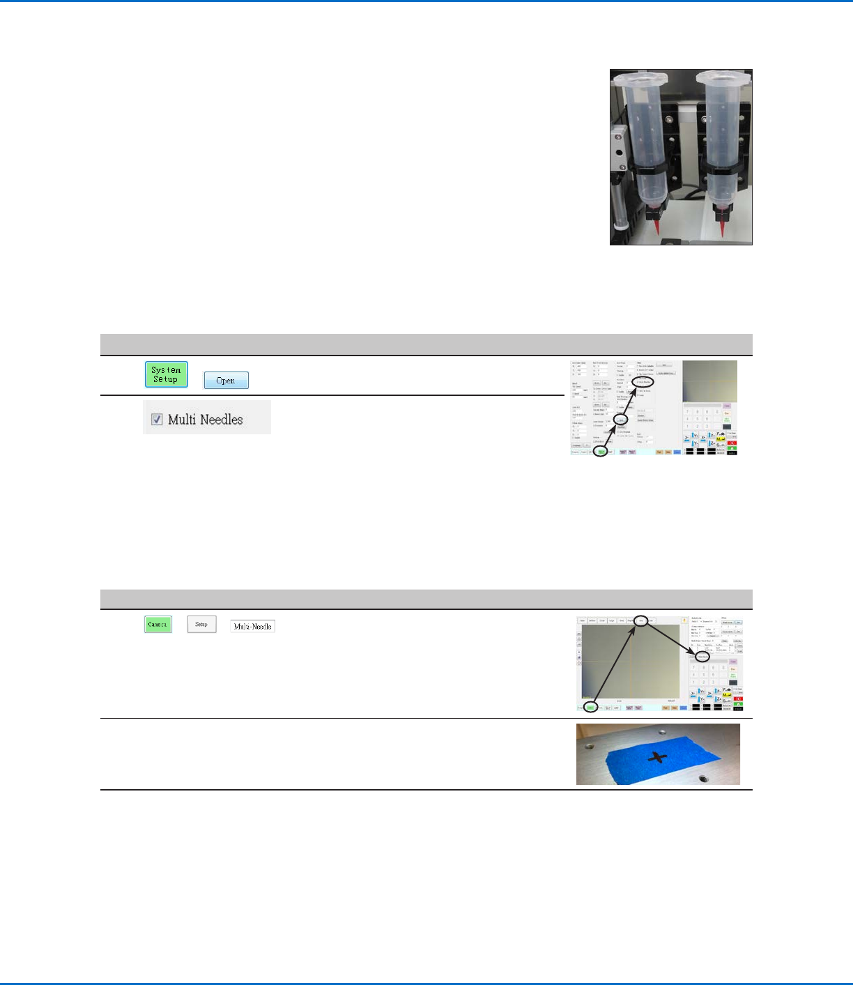
• Click the CAMERA tab, click SETUP at the
top of the Camera screen, and then click the
MULTI-NEEDLE tab.
The Multi Needle fields appear.
2 • If your system does not include the tip
detector, create a crosshair target point close
to the workpiece.
Continued on next page
AppendixE, Multi-Needle Setup and Use
A multi-dispenser bracket can be installed on the Zaxis to accommodate up to four
dispensers. When more than one dispenser is installed, the camera-to-tip offset must
be set for each dispenser. After the system is set up for multi-needle operation, you can
insert the Multi Needle dispense command to specify which dispenser executes the
commands that follow the Multi-Needle command.
NOTE: For contact dispensing applications with multiple dispensers, an additional toggle
assembly is required for the multi-dispenser bracket.
PREREQUISITES
The required additional dispensers are installed on the robot. Contact your Nordson
EFD representative for assistance as needed.
The system is properly set up. Refer to “Setting Up and Calibrating the System (Required)” on page45.
A test workpiece is positioned on the fixture plate or work surface.
To Enable Multi-Needles Dispensing
#
Click Step Reference Image
1
>
• Click the SYSTEM SETUP tab, then click
OPEN.
2 • Check MULTI NEEDLES.
RV Series Automated Dispensing Systems
138 www.nordsonefd.com info@nordsonefd.com +1-401-431-7000 Sales and service of Nordson EFD dispensing systems are available worldwide.
# Click Step Reference Image
3
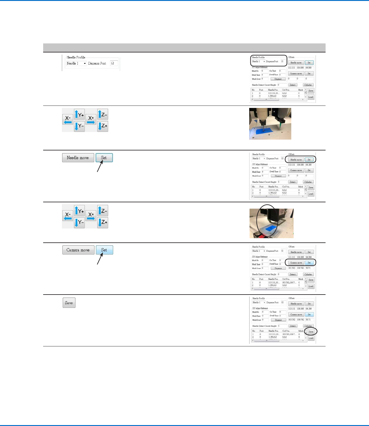
• Enter the following information for NEEDLE
PROFILE:
- Dispenser number (in this example,
Needle1 for Dispenser 1)
- Port that the dispenser is connected to
(in this example, Dispense Port 12 for
Dispenser 1)
4 • Use the jog keys to position the tip over the
crosshair target (on either the tip detector or
the one you created).
• Jog the tip down until it as close to the
crosshair target as possible without touching
the target.
5 • Click SET next to Needle Move.
This sets the XYZR coordinates for the
dispense calibration point. The system enters
the dispensing tip coordinates in the fields
under Needle Move and Set.
6 • Jog the camera until the camera crosshairs
are centered over the crosshair target,
then
focus the camera until the image of the
crosshair target is clear.
7 • Click SET next to Camera Move.
This sets the camera position. The system
enters the camera coordinates in the fields
under Camera Move and Set.
8 • Click SAVE.
The system populates the Needle 1 data
fields.
Continued on next page
AppendixE, Multi-Needle Setup and Use (continued)
To Set the Camera-to-Tip Offsets for Multiple Dispensers (continued)
RV Series Automated Dispensing Systems
139www.nordsonefd.com info@nordsonefd.com +1-401-431-7000 Sales and service of Nordson EFD dispensing systems are available worldwide.
AppendixE, Multi-Needle Setup and Use (continued)
To Set the Camera-to-Tip Offsets for Multiple Dispensers (continued)
# Click Step Reference Image
9
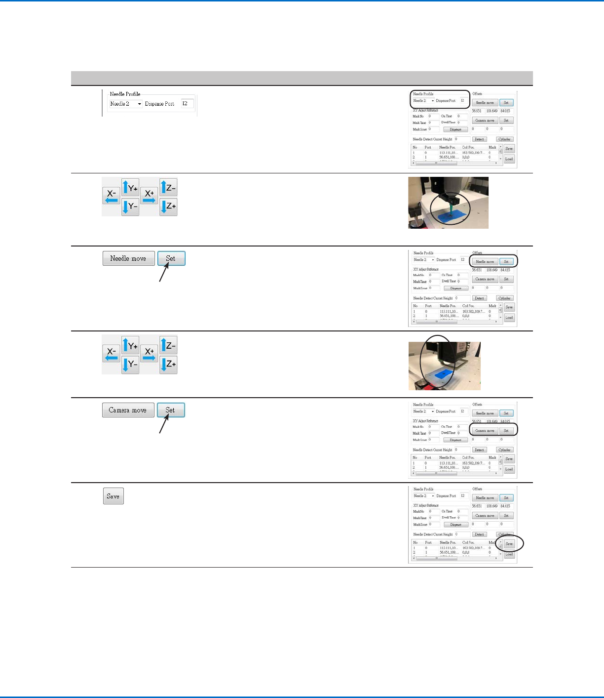
• Enter the following information for NEEDLE
PROFILE:
- Dispenser number (in this example,
Needle2 for Dispenser 2)
- Port that the dispenser is connected to
(in this example, Dispense Port 12 for
Dispenser 2)
10 • Use the jog keys to position the second tip
over the crosshair target (on either the tip
detector or the one you created).
• Jog the tip down until it as close to the
crosshair target as possible without touching
the target.
11 • Click SET next to Needle Move.
This sets the XYZR coordinates for the
dispense calibration point. The system enters
the dispensing tip coordinates in the fields
under Needle Move and Set.
12 • Jog the camera until the camera crosshairs
are centered over the crosshair target
and then
focus the camera until the image of the
crosshair target is clear.
13 • Click SET next to Camera Move.
This sets the camera position. The system
enters the camera coordinates in the fields
under Camera Move and Set.
14 • Click SAVE.
The system populates the Needle 2 data
fields.
The system is now set up for multiple dispenser
operation. Continue to the next procedure in
this section to use this capability.