Vista Rail System Module.pdf - 第10页
5$,/ 6< 67(0 02' 8/( 6(48(1&(6 12.10 Technical Reference Manual Chapter Issue 1 Sep 02 SEQUENCES Homing Sequence The rail syst em is homed during machine initializa tion only , (during power-up or upon exit…
5$,/6<67(002'8/(
'5,9(6$1'6(16256
Chapter Issue 1 Sep 02 Technical Reference Manual 12.9
Board at Left/Right
Sensors
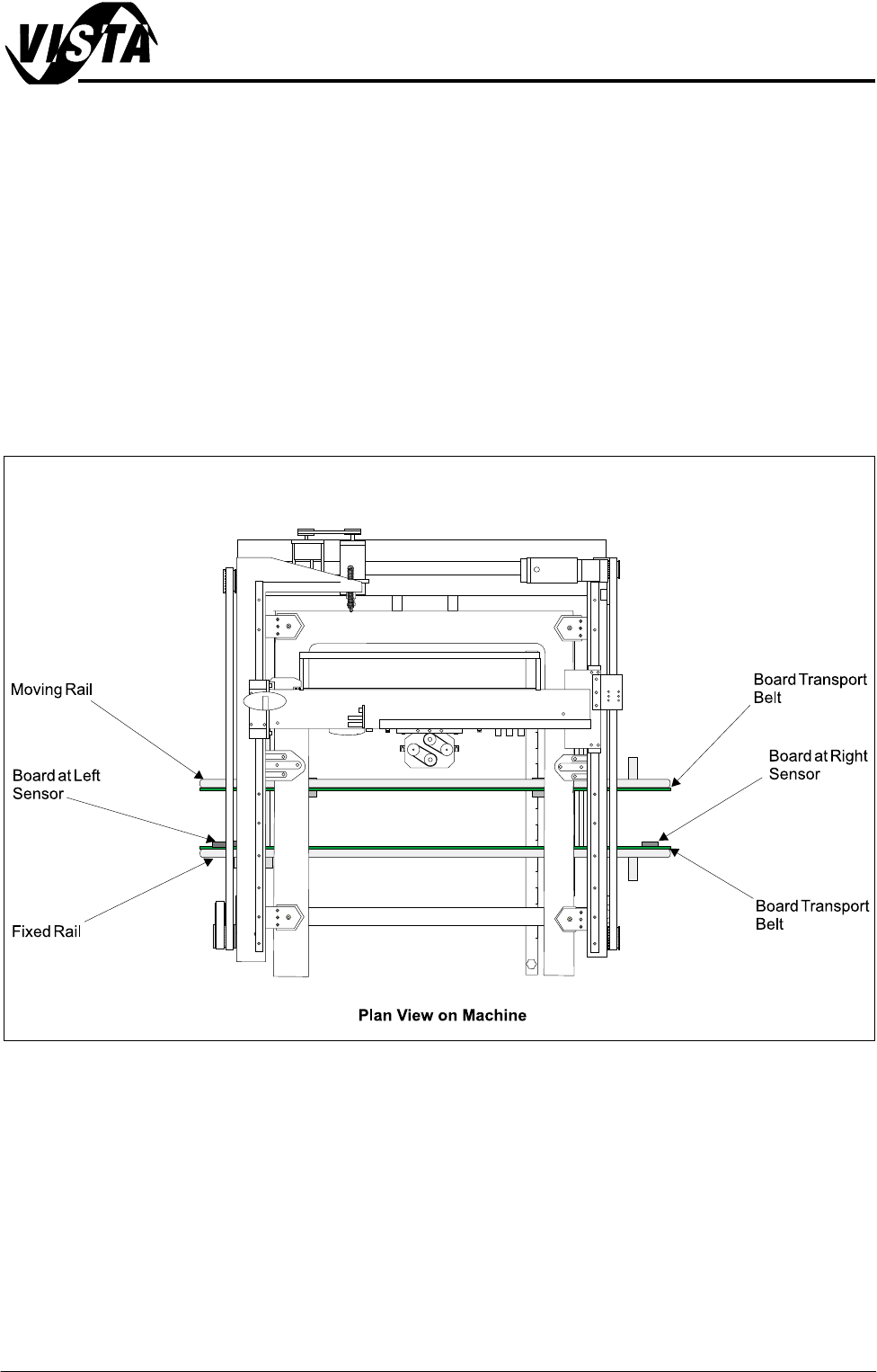
The board at left and board at right sensors are diffuse opto type sensors.
These two sensors are used to detect a board at the input and output of the
transport belt. As the machine is bi-directional the functions of both optos are
reversed when the pass through direction is changed.
The input sensor is used to start the transport belt on detection of a board. The
board is transported into the machine and processed after which it is transferred
to the output sensor where it stops and waits for the command to be passed
onto the next machine in the line.
These optos are fitted with a red and green LED along with a sensitivity control.
There is a small amount of positional adjustment in the bracket but generally it
is not necessary to reset it as the footprint used by the diffuse opto is large
enough to cope with the holes in an average production board.
Figure 12-6 Board at Left/Right Opto Locations
5$,/6<67(002'8/(
6(48(1&(6
12.10 Technical Reference Manual Chapter Issue 1 Sep 02
SEQUENCES
Homing Sequence The rail system is homed during machine initialization only, (during power-up or
upon exiting diagnostics).
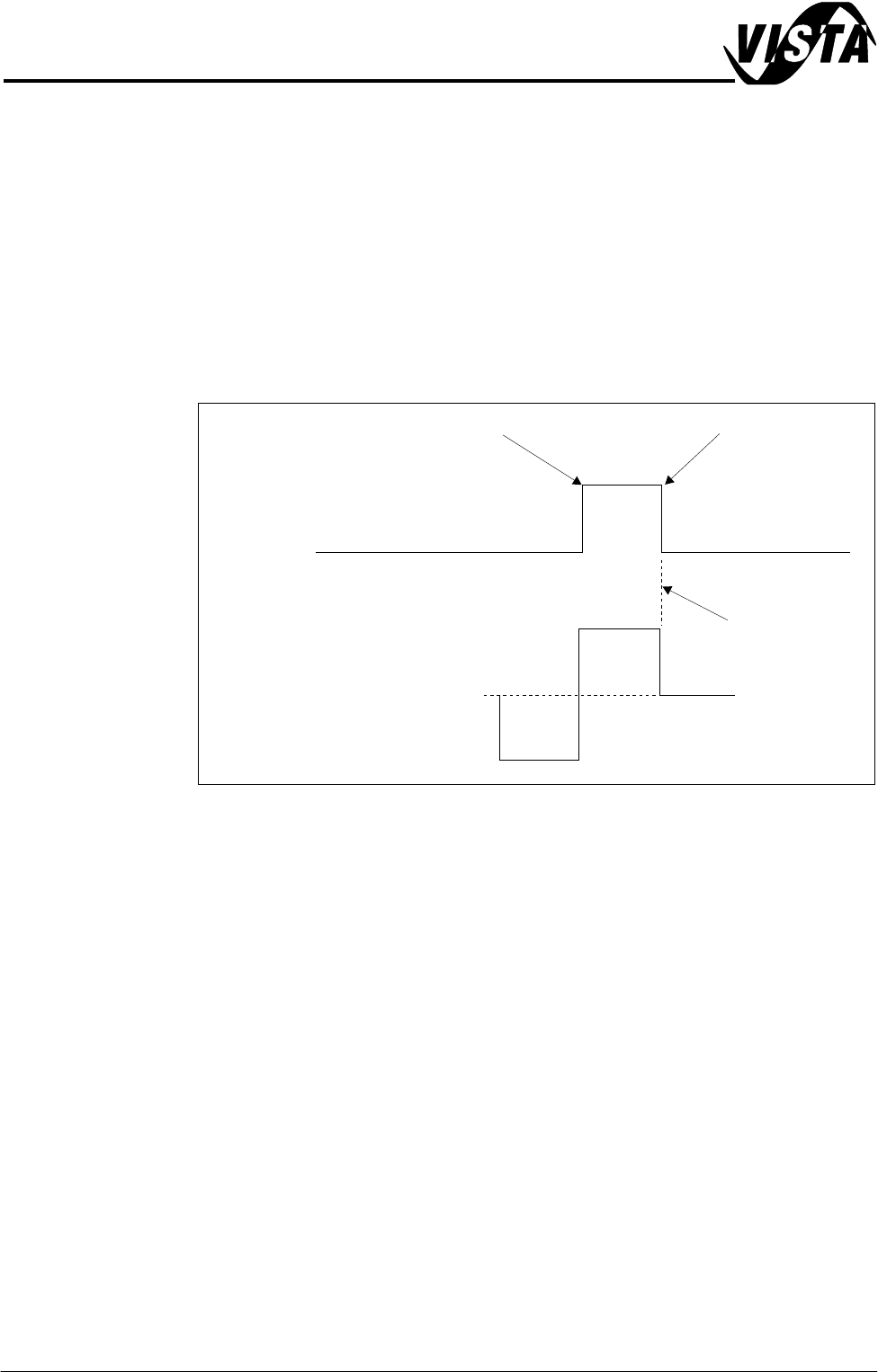
When the home command is received the rear moving rail is driven (in the
reverse direction) to the rear of the machine until the home vane, attached to it,
is detected by the rail home sensor. Upon detection (sensor ON) the motor is
driven in the opposite direction until the vane clears the home sensor and the
motor stops (sensor OFF).
This position has a set dimension of 609.5mm to 610.5mm measured between
the inside of each rail, (Positioning section of this chapter refers)
Figure 12-7 Rail Timing Diagram
Rail Positioning There is a fixed relationship between steps of the stepper drive motor and rail
movement (in mm) due to the gearing ratios and pitch of the driving leadscrews.
Therefore when a width is selected this is multiplied by the steps/mm factor and
sent to the stepper drive system.
All positions are relative to the home position.
Home Position
Fwd
Stepper
Motor
Home
Sensor
0V
12V
Stopped
Rev
Vane leaves sensor
Vane enters sensor
5$,/6<67(002'8/(
$'-8670(176$1'6(7 7,1*6
Chapter Issue 1 Sep 02 Technical Reference Manual 12.11
ADJUSTMENTS AND SETTINGS
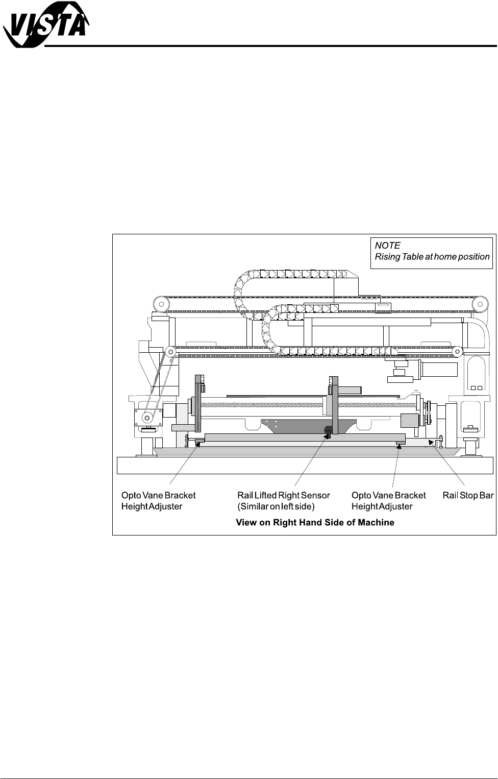
Rail Lifted Sensors Both the left and right rail lifted sensors are through beam optos and mounted
either side of the rising table so to detect premature lifting of the rear rail, as
described in the Drives and Sensors section of this chapter.
The opto vane brackets are height adjustable and are set using a 0.5mm feeler
gauge, so that if either opto is moved by a minimum of 0.5mm above the vane
setting (whilst the table is in the home position), then the LED switches to OFF
indicating an error warning to the operator.
NOTE
Rail Lift Setting figure of this chapter also refers.
Figure 12-8 Rail Lifted Sensor Location
Rail Width Home
Sensor
The rail width home sensor is used to find the home position of the moving rail
and is described in detail in the Sequences section (Homing Sequence) of this
chapter.
The sensor is mounted on an adjustable bracket which enables the position
between the front and rear rails to be set to 609.5 - 610.5mm, (measured
between the inside edges of both rails, when the moving rail is in the home
position).
A fine adjustment can be made to the set rail dimension by slackening the
sensor forward securing screw and turning the home sensor adjustment screw
(Figure Rail Home Setting refers) in accordance with the table on the next page.