Vista Rail System Module.pdf - 第22页
5$,/ 6<67( 002' 8/( &$/,%5$7,21 6 12.22 Technical Reference Manual Chapter Issue 1 Sep 02 3. Using a tachometer fitted wi th the surf ace speed test wheel, positioned on the input or output pulley of the fr…
5$,/6<67(002'8/(
&$/,%5$7,216
Chapter Issue 1 Sep 02 Technical Reference Manual 12.21
CALIBRATIONS
Board Transport
Belt Speed
The front and rear board transport belts (feeder belts) are driven independently
by two variable speed motors. Inevitably one motor drives faster than the other
motor. It is necessary to calibrate these motors so that they drive at the same
speed in either direction.
WARNING
LETHAL VOLTAGE. DANGEROUS VOLTAGES EXIST IN THIS EQUIPMENT.
ENSURE ALL ELECTRONIC COVERS AND MAIN MACHINE COVERS ARE
FITTED BEFORE OPERATING THIS EQUIPMENT.
The speed of both feeder belt motors is controlled by a MultiMove card situated
in the machine control enclosure and utilizes Pulse Width Modulation (PWM).
This is achieved by controlling the period of the ’ON’ control pulse provided by
the MultiMove control card. The pulse repetition rate is fixed at 125Hz.
Feeder motor speed is measured using a tachometer on the input or output
pulley and adjusted by using the Belt Speed Calibration Page in the machine
diagnostics.
NOTE
For belt speed calibration set up see Calibration Procedure of this section. For
detailed information on access and use of the diagnostics module refer to the
Diagnostics chapter of the User manual.
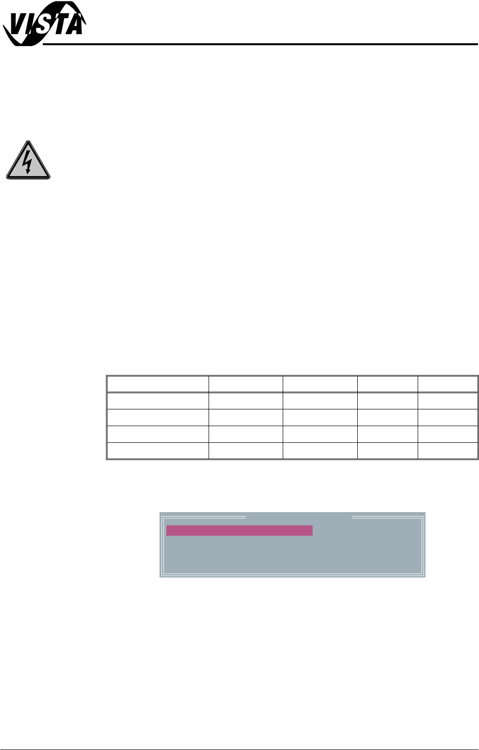
Motor speed software parameters is listed in the following table:
Calibration
Procedure
1. In Diagnostics, select Rail System.
2. Select Belt Speed Calibration, the following window is displayed:
Name Maximum Minimum Default Increment
Front L to R Speed 64000 0 32000 1
Rear L to R Speed 64000 0 32000 1
Front R to L Speed 64000 0 32000 1
Rear R to L Speed 64000 0 32000 1
Belt Speed Calibration
50000
50000
63999
63999
FRONT L TO R SPEED
FRONT R TO L SPEED
REAR L TO R SPEED
REAR R TO L SPEED
5$,/6<67(002'8/(
&$/,%5$7,216
12.22 Technical Reference Manual Chapter Issue 1 Sep 02
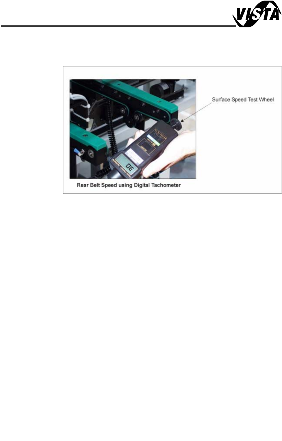
3. Using a tachometer fitted with the surface speed test wheel, positioned on
the input or output pulley of the front belt motor, measure the speed of the
motor left to right. Adjust the motor speed using Incr./Decr. to achieve a
speed of 29 - 31 metres/min.
4. Using Next repeat Step 3 for front right to left motor speed.
5. Select Next use a tachometer fitted with the surface speed test wheel,
positioned on the input or output pulley of the rear belt motor, measure the
speed of the motor left to right. Adjust the motor speed using Incr./Decr. to
achieve a speed of 29 - 31 metres/min.
6. Using Next repeat Step 5 for rear right to left motor speed
7. Select Save, the speed of the front and rear belt motors are now saved in
the machine configuration file.
8. Select Exit.
9. Select Exit.
10.Select Exit.

5$,/6<67(002'8/(
7(67&<&/(6
Chapter Issue 1 Sep 02 Technical Reference Manual 12.23
TEST CYCLES For information on the Test Cycles function refer to the Screen Alignment
Chapter of this manual.