Vista Rail System Module.pdf - 第5页
5$,/6< 67(002' 8/( 0(&+$ 1,&$/'( 7$,/ Chapter Issue 1 Sep 02 Technical Reference Manual 12.5 Foil-le ss Clamp s This option is used on thi n boards which are populat ed with component s too close …
5$,/6<67(002'8/(
0(&+$1,&$/'(7$,/
12.4 Technical Reference Manual Chapter Issue 1 Sep 02
MECHANICAL DETAIL
Belt Drive The board is transported on ‘O’ ring type belting which is driven by two moving
coil motors, one on each rail.
The speed of these motors is controlled by a MultiMove card in the machine
controller which can be adjusted via the machine diagnostics (Belt Speed
Calibration page).
NOTE
For belt speed calibration refer to the Calibrations Section of this chapter.
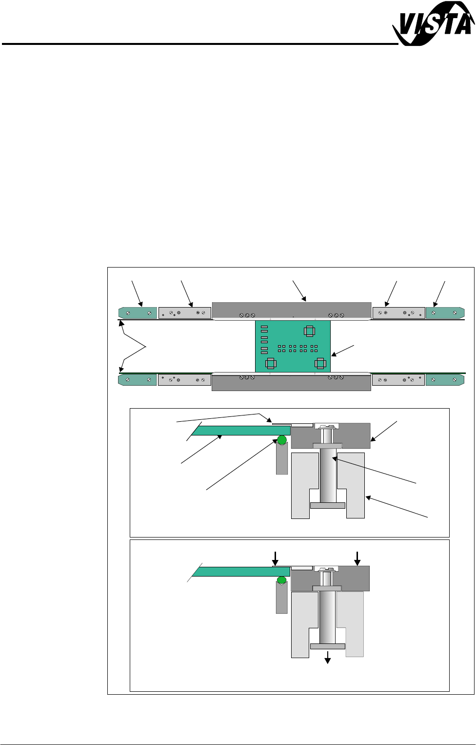
Board Clamps A board clamping arrangement is utilized to minimize board distortion during
print process. A pneumatically operated piston, (via a 24v switched solenoid
16SOL10 from the machine controller), lowers the board clamp and foil trapping
the board on the transport belts. On completion of the print stroke the board is
released by activation of the pneumatic solenoid.
Figure 12-2 Board Clamping Arrangement
Transport Belts
Pneumatic Piston Driven Downwards
WARNING-SHARP EDGE
PATENT No.5157438
End Rail End RailMid Rail Mid RailBoard Clamp
Board
Board Trapped Between Foil and Transport Belt
Plan View of Rail System
Transport Belt
Rail
Piston
Metal Foil
Board Clamp
Board
Board Free on Transport Belt
Board Clamp and Foil Lowered
WARNING-SHARP EDGE
PATENT No.5157438
5$,/6<67(002'8/(
0(&+$1,&$/'(7$,/
Chapter Issue 1 Sep 02 Technical Reference Manual 12.5
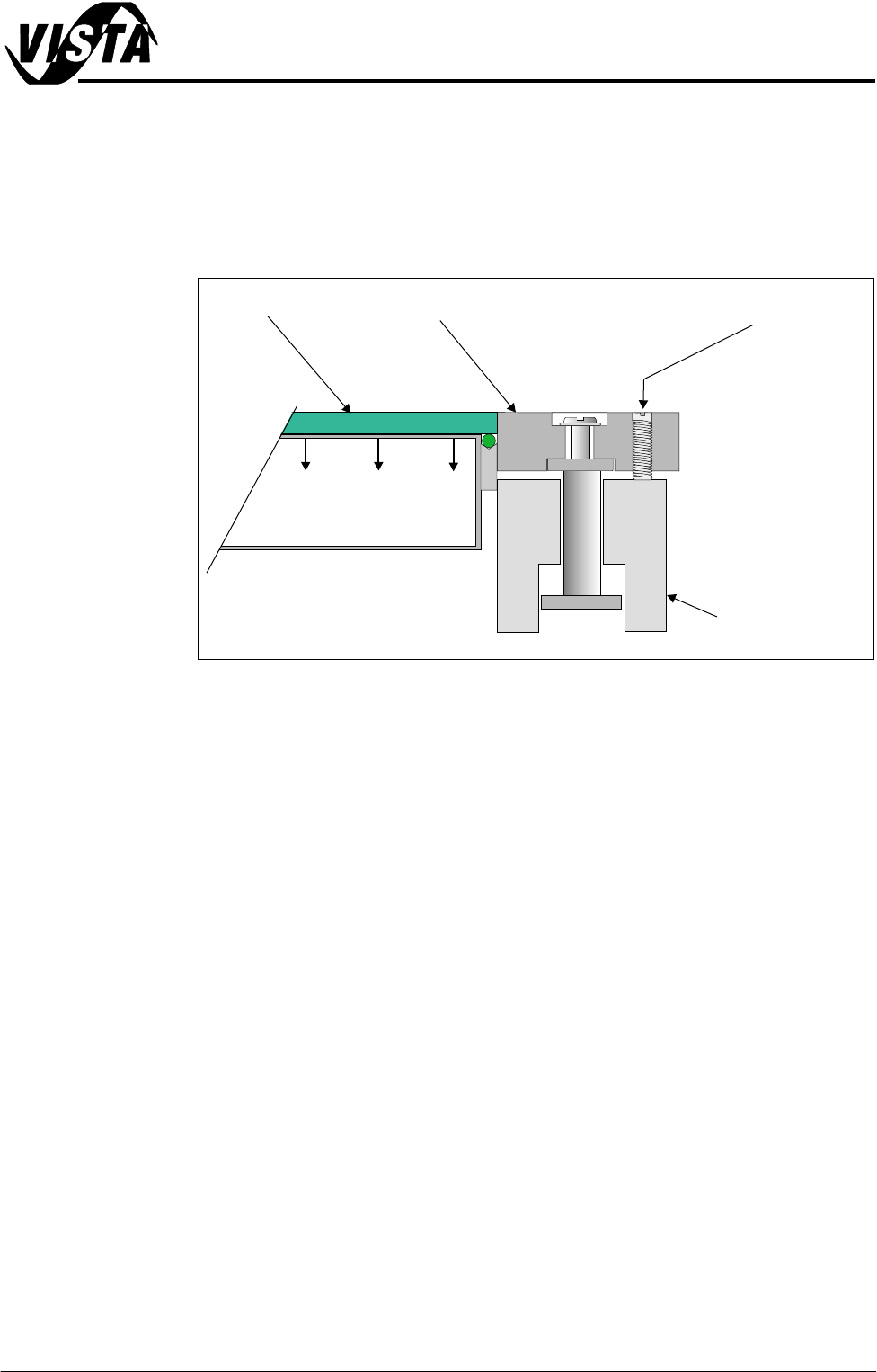
Foil-less Clamps This option is used on thin boards which are populated with components too
close to the edge of the board for traditional board clamps. The board is
secured during the print stroke by the use of vacuum. The clamps are
perpendicular to the board maintaining a good gasket between the board and
the stencil. The clamps are adjusted in height for different thicknesses of board
by two grub screws.
Figure 12-3 Side View of Foil-less Clamp Operation
Adjustment Grub Screw
Rail
Foil-less Clamp
Board
Vacuum Box
5$,/6<67(002'8/(
'5,9(6$1'6(16256
12.6 Technical Reference Manual Chapter Issue 1 Sep 02
DRIVES AND SENSORS
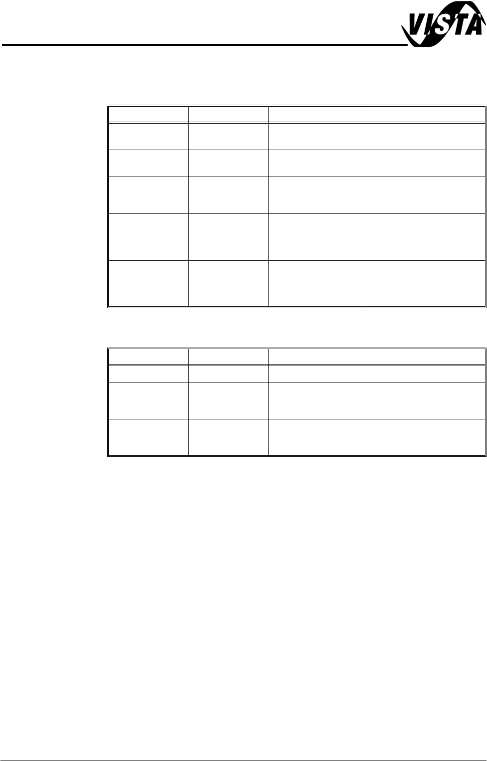
Sensors
Motors
NOTE
Location of rail system sensors and drives are detailed on the Rail System
Overview Figure at the beginning of this chapter.
Name Type Test Point Functional Description
Rail Lifted Left Through Beam
Opto
NextMove Dig IN 3 Detects premature lifting of
rail
Rail Lifted Right Through Beam
Opto
NextMove Dig IN 4 Detects premature lifting of
rail
Moving Rail Home Through Beam
Opto
Stepper Multiplexer
MUX2
Provides home position of
moving rail thus providing
accurate board width settings
Board at Left Diffuse Opto NextMove Dig IN 16 Detects left side incoming/
outgoing board dependent
upon machine pass through
configuration
Board at Right Diffuse Opto NextMove Dig IN 17 Detects right side incoming/
outgoing board dependent
upon machine pass through
configuration
Name Type Functional Description
Moving Rail Drive Stepper Motor Moves the rear moving rail in the Y direction
Front Board
Transport Belt
Drive
DC Moving Coil
Motor
Turns the front transport belt in the clockwise or anti
clockwise direction (dependent upon upline/downline
feed direction)
Rear Board
Transport Belt
Drive
DC Moving Coil
Motor
Turns the rear transport belt in the clockwise or anti
clockwise direction (dependent upon upline/downline
feed direction)