Vista Rail System Module.pdf - 第8页
5$,/ 6< 67(0 02' 8/( '5,9(6$ 1'6(16 256 12.8 Technical Reference Manual Chapter Issue 1 Sep 02 Rail Home Sensor The rail home sensor is a through beam opto type sensor . The sensor i s used for ac c…
5$,/6<67(002'8/(
'5,9(6$1'6(16256
Chapter Issue 1 Sep 02 Technical Reference Manual 12.7
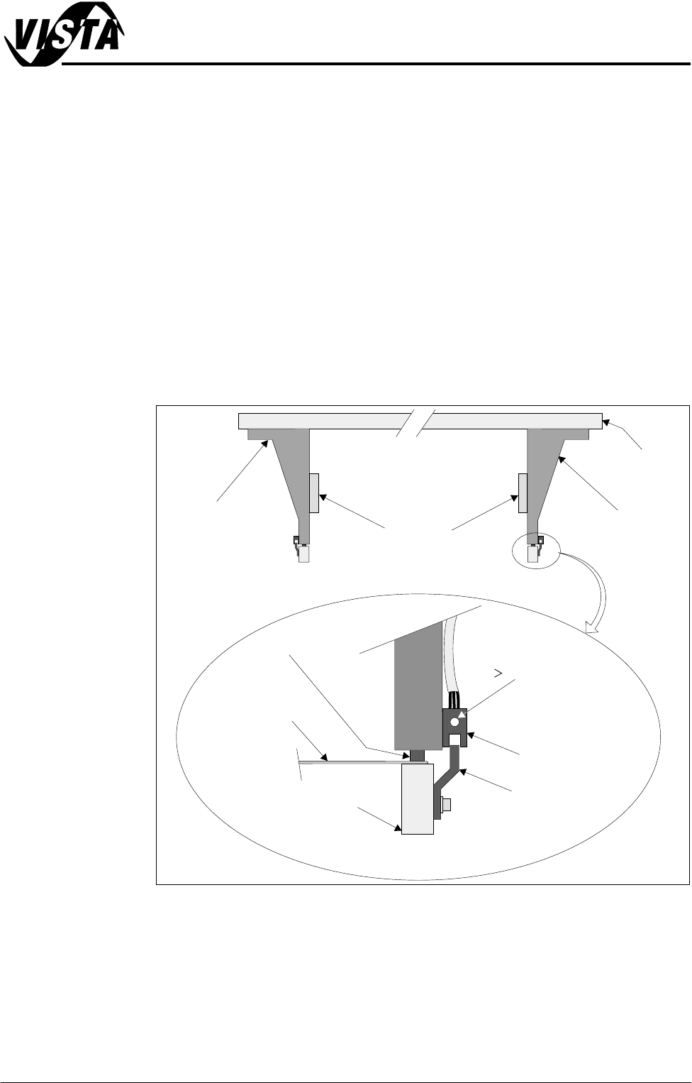
Rail Lifted Sensors The left and right rail lifted sensors are through beam opto type sensors.
These sensors are fitted to the bottom of the left and right moving rail support
arms. The sensor vanes are fitted to the entire length of the rail stop bars.
These sensors feed directly into NextMove card of the machine PC.
The purpose of the rail lifted sensors is to detect premature lifting of the rail as
the rising table rises. This may occur if tooling or any other object was placed
under the rear rail. They are checked:
1. Immediately after the rail has moved to its new board width following product
file change.
2. When Run is pressed, before the camera moves to board stop position.
3. After printing to check that the rail is fully down before the next print cycle
can commence.
4. When the table moves to rail lift check height before moving to vision height.
Figure 12-4 Rail Lift Setting
Right Rail
Support Bracket
Main Rear
Rail
Front View of Rail System
Left Rail
Support Bracket
Feeler Gauge -
0.5mm
Rail Stop Bar
Opto Vane
Bracket
Opto
Shock Absorber
Light Extinguishes
when Sensor lifted
0.5mm
Linear Rail
Enlarged View of Right Rail Opto
5$,/6<67(002'8/(
'5,9(6$1'6(16256
12.8 Technical Reference Manual Chapter Issue 1 Sep 02
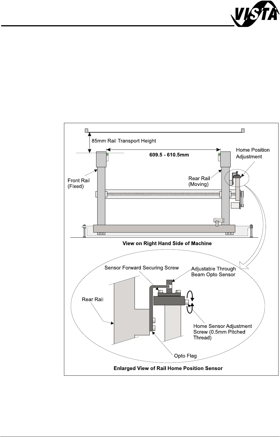
Rail Home Sensor The rail home sensor is a through beam opto type sensor.
The sensor is used for accurately determining the front and rear rail widths.
During machine initialization, (power-up or upon exiting diagnostics), the rear
rail moves to the rear of the machine where upon the rail opto vane enters the
rail home sensor, the rear rail is now at the home position.
NOTE
Homing Sequence of this chapter refers.
The rail home sensor feeds directly to the Multiplexer controller and is used to
set the datum value for the rail width (609.5mm - 610.5mm).
Figure 12-5 Rail Home Setting
5$,/6<67(002'8/(
'5,9(6$1'6(16256
Chapter Issue 1 Sep 02 Technical Reference Manual 12.9
Board at Left/Right
Sensors
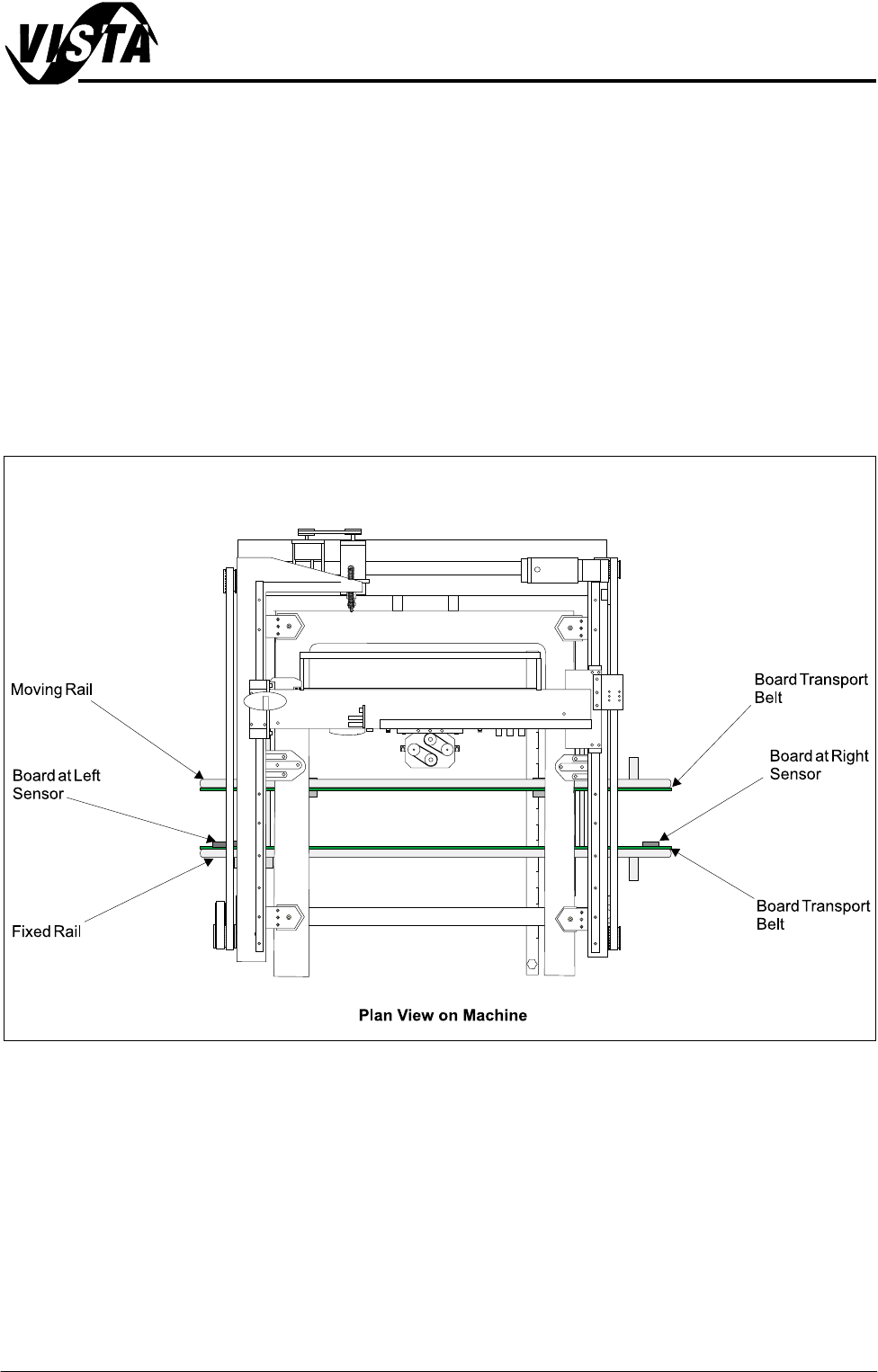
The board at left and board at right sensors are diffuse opto type sensors.
These two sensors are used to detect a board at the input and output of the
transport belt. As the machine is bi-directional the functions of both optos are
reversed when the pass through direction is changed.
The input sensor is used to start the transport belt on detection of a board. The
board is transported into the machine and processed after which it is transferred
to the output sensor where it stops and waits for the command to be passed
onto the next machine in the line.
These optos are fitted with a red and green LED along with a sensitivity control.
There is a small amount of positional adjustment in the bracket but generally it
is not necessary to reset it as the footprint used by the diffuse opto is large
enough to cope with the holes in an average production board.
Figure 12-6 Board at Left/Right Opto Locations