YS24 保养手册.pdf - 第10页
3-8 3 Periodic maintenance items 2.2 Inspecting each axis (monthly) Inspect the ball screws on the X, W , U, and PU axes and the linear guides on the X, Y , W , and U axes. The chec kpoints are listed below . n NOTE A gr…
3-7
3
Periodic maintenance items
2. Monthly or bimonthly inspection
This section mainly explains the cleaning and lubrication procedures after inspection.
2.1 Cleaning the nozzle air path (monthly)
e
1
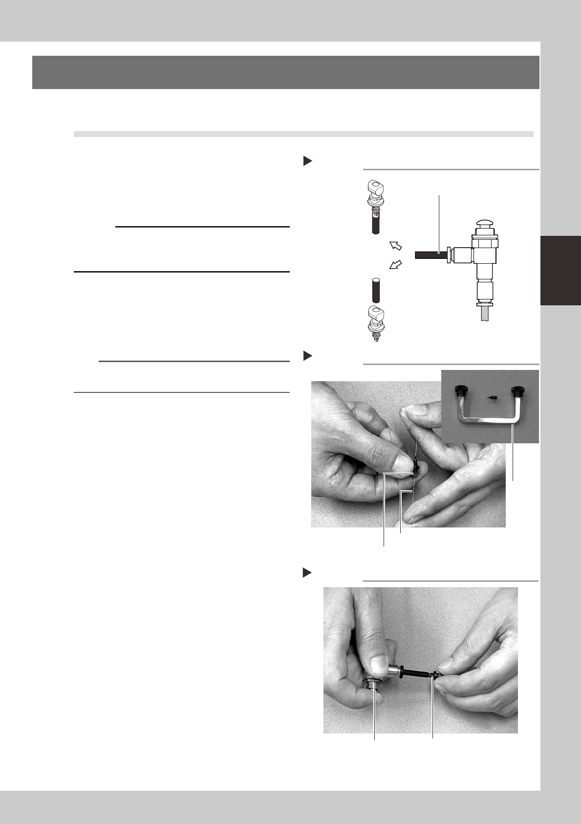
Remove the nozzle from the head.
Always first press the emergency stop button
and then remove the nozzle from the head.
The machine must be in emergency stop to
ensure safety during work.
c
When the machine is equipped with a nozzle station
nozzle station after cleaning.
2
Blow air through the nozzle.
Using an air blow tool, blow air through the
nozzle from the nozzle tip and then from the
other end.
53310-L2-00
n
NOTE
If there are dust deposits in the nozzle, perform steps 3
and 4.
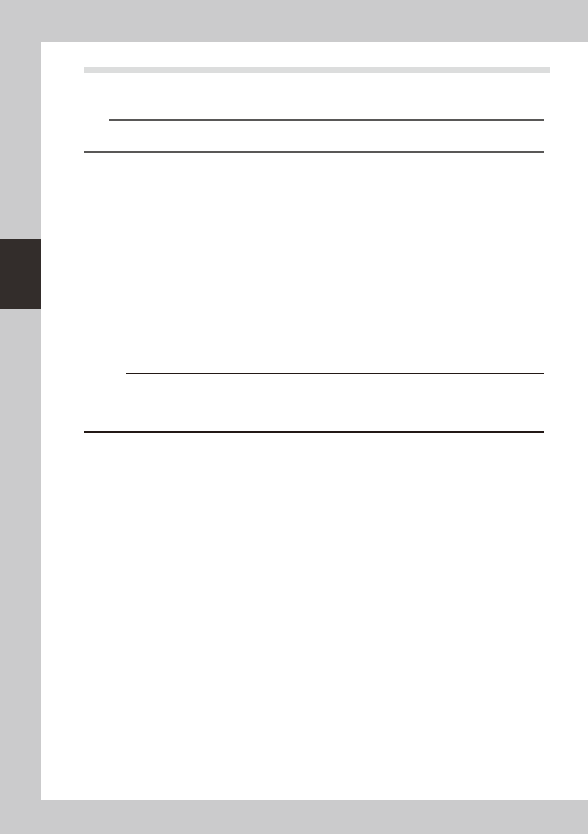
3
Clean the nozzle hole.
Pass the nozzle cleaning wire through the
nozzle hole and clean the nozzle hole. While
holding both ends of the wire with fingers as
shown or using a custom handle (option),
gently move the nozzle back and forth.
53311-L2-00
4
Blow air onto the nozzle tip again.
After removing the cleaning wire, blow air
through the nozzle with the air blow tool, just
as in step 2.
53312-L2-00
Following the nozzle cleaning above, check and
clean the spring-action parts. (See 1.1.1, "Checking
and cleaning the spring-action parts" described
earlier in this chapter.)
Air blow
Step 2
Air tube (black)
Air blow tool
(option)
Air tube (orange) connected to
air supply port
Insert the
nozzle tip into
the air tube and
blow air.
Blow air from the
nozzle attachment
side.
Cleaning a nozzle
Step 3
Custom
handle
(option)
Nozzle
Nozzle cleaning wire
Air blow
Step 4
NozzleAir blow gun (option)
3-8
3
Periodic maintenance items
2.2 Inspecting each axis (monthly)
Inspect the ball screws on the X, W, U, and PU axes and the linear guides on the X, Y, W, and U axes. The
checkpoints are listed below.
n
NOTE
A grease spattering prevention cover is attached to the X-axis. Before starting the inspection work, detach this grease
spattering prevention cover while referring “Detaching grease spattering prevention cover” described later on.
Checkpoints
1. Any foreign matter adhering to the ball screws and linear guides?
Check if any fallen chips have adhered to the X and Y axis ball screws and/or X, Y and W axis linear guides.
2. Do the ball screws and linear guides have the correct amount of grease?
Check if grease has flowed off or splattered in the air failing to adhere. Also check if grease has discolored or hardened.
e
3. Any abnormal sounds from the ball screws?
Press the emergency stop button. Then check for any abnormal sounds while pressing the X-axis by hand.
Countermeasures
1. Ball screws and linear guides may be damaged when chips and other material bite into them. If chips are adhering,
wipe them off along with the grease or remove with tweezers, etc.
2. Apply grease while referring “Cleaning and lubrication” described later on.
3. Consult your YAMAHA sales office or representative when abnormal sounds occur even after trying the
countermeasures in the above steps 1 and 2.
c
understand its contents.
3-9
3
Periodic maintenance items
2.3 Cleaning and greasing the X, Y, and PU axes (bimonthly)
This section describes how to clean and grease the X, Y, and PU axes. For details about lubrication points and
procedures, see the section, “Lubrication points”, in Chapter 4. Prepare the grease gun and specified grease
(NSL).
c
c
grease" in Chapter 1.
c
the warranty.
2.3.1 Cleaning and greasing the X-axis ball screw
e
1
Make the preparations for the
cleaning and greasing work.
1. Take off all accessories susceptible to the
magnetic fields, such as a wristwatch
and/or magnetic ID card.
2. Press the emergency stop button to put
the machine in the emergency stop
state.
3. Put square bandages on the Y-axis linear
guide and push-up plate.
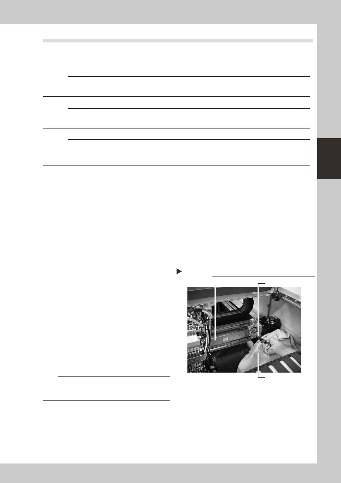
2
Remove the grease spattering
prevention cover.
Remove the X-axis grease spattering
prevention cover.
1. Use a Phillips screwdriver to remove the
screws securing the left side of the
grease spattering prevention cover.
2. Move the head all the way to the left
side and remove the screws securing the
right side of the grease spattering
prevention cover.
3. Remove the grease spattering prevention
cover by pulling it to the right.
53305-L2-00
TIP
When reattaching the X-axis grease spattering
prevention cover, use the reverse order of the above
procedure.
Removing the X-axis grease spattering prevention cover
Phillips screwdriver
Square bandage
Grease spattering prevention cover
Step 2