YS24 保养手册.pdf - 第31页
3-29 3 Periodic maintenance items 4.2 Cleaning the scan camera lighting unit (6-month inspection) T he light diffuser plate and prism for the scan camera are attached to the opening at the left end of the camera. T hese …
3-28
3
Periodic maintenance items
4. Six-month or one-year inspection
4.1 Cleaning the fiducial camera lighting unit (6-month inspection)
The lighting unit may become dirty due to dust and dirt. We recommend periodic cleaning as explained below.
To ensure safety, make sure that the machine power switch is off or the emergency button is pressed before
starting work.
c
become unreliable.
c
of the lighting unit by the user will void the warranty.
n
Fiducial mark recognition camera
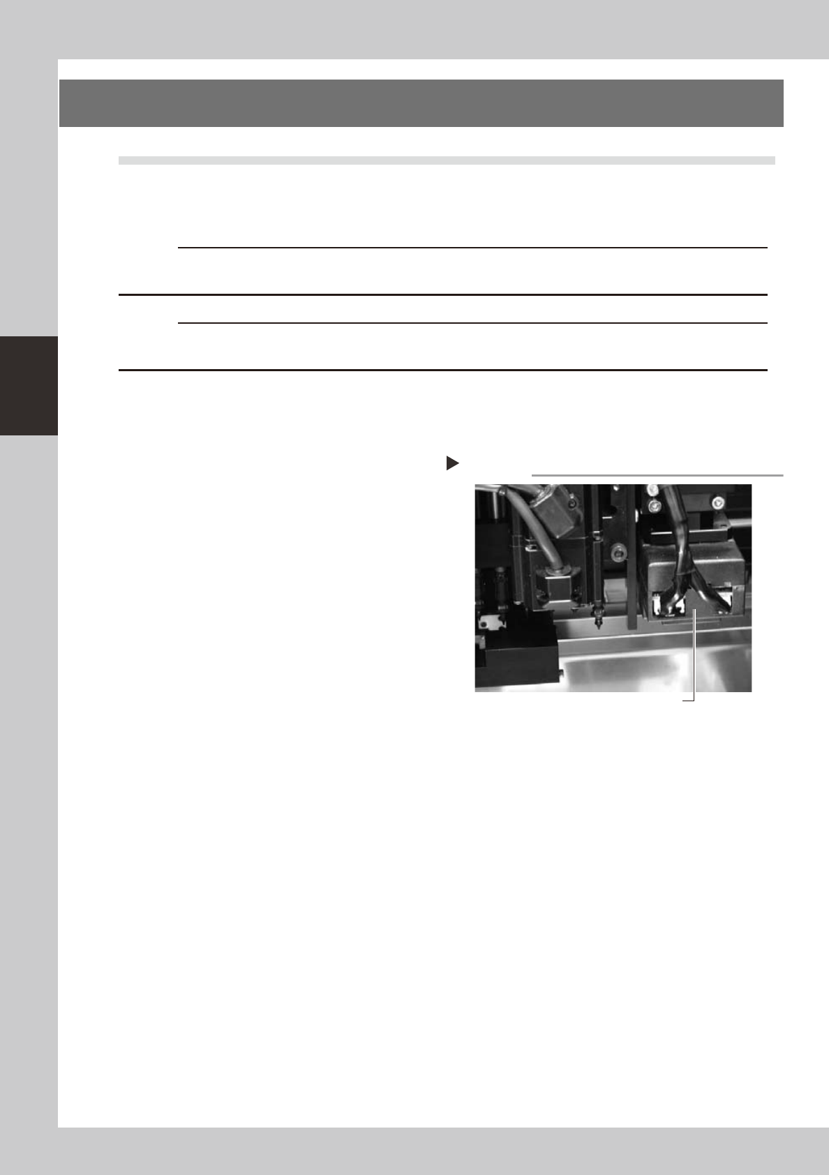
The fiducial mark recognition camera is mounted on the head assembly. Clean the lighting unit for this camera
as explained below.
• Cleaning method
Apply a few drops of lens cleaner to a lint-free
cleaning cloth and wipe the diffuser plate on the
bottom of the lighting unit.
53337-L2-00
Wipe with cleaning cloth.
Lighting unit for fiducial mark camera
3-29
3
Periodic maintenance items
4.2 Cleaning the scan camera lighting unit (6-month inspection)
The light diffuser plate and prism for the scan camera are attached to the opening at the left end of the camera.
These diffuser plate and prism may become dirty due to dust and dirt. Periodic cleaning is recommended.
c
the camera unit.
1
Return all nozzles to the nozzle station.
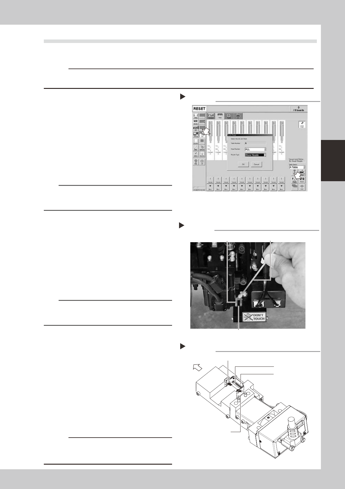
1. Press the [Unit] button and open the
[Head] tab. Then press the [Nozzle
Change] button.
2. In the "Nozzle Change" dialog that
appears, select "ALL" from the "Head
Number" drop-down list and select "Store
Nozzle" from the "Nozzle Type" drop-down
list.
3. Press the [OK] button to return all nozzles
to the nozzle station.
54312-L2-00
n
NOTE
If the machine does not have a nozzle station, press the
emergency stop button and then detach the nozzles
by hand.
e
2
Move the head unit.
Press the emergency stop button and then
move the head unit to a position where
cleaning can be carried out easily.
3
Move the scan camera.
1. Move all heads (nozzle holder sections)
by hand to their upper ends.
2. Move the scan camera to the right side
of the R-axis motor. At this point, do not
apply excessive force to the scan
camera.
n
NOTE
When the machine has only one fiducial camera,
moving the scan camera to an opposite side will make
the cleaning work easier.
4
Wipe the diffuser plate and prism.
1. Use a cotton swab to remove dust and
dirt on the upper surface of the main
light diffuser plate and on the prism
surface. Since the prism surface is
narrow, twist the end of the cotton swab
into a pointed tip and use it to wipe the
prism surface lightly.
2. Wipe the side-view light diffuser plate
and prism using a cotton swab. Use a
hand mirror when wiping the prism
surface since it cannot be seen from the
front.
53360-L2-00
53361-L2-00
c
of the prism to peel or flake and the diffuser plate to
discolor.
Cleaning the light diffuser plate and prism
Step 4
Light diffuser plate
Prism
Cotton swab
Cleaning points of light diffuser plate and prism
Main diffuser plate
Side-view diffuser plate
Side-view prism
Front of machine
Main prism
Returning all nozzles to nozzle station.
Step 1
3-30
3
Periodic maintenance items
4.3 Cleaning and greasing the W axis (6-month inspection)
This section describes how to clean and grease the W axis. For details about lubrication points and procedures,
see the section, “Lubrication points”, in Chapter 4. Prepare the specified grease (NSL).
4.3.1 Cleaning and greasing the W-axis ball screw
1
Make the preparations for the
cleaning and greasing work.
Take off all accessories susceptible to the
magnetic fields, such as a wristwatch and/
or magnetic ID card.
2
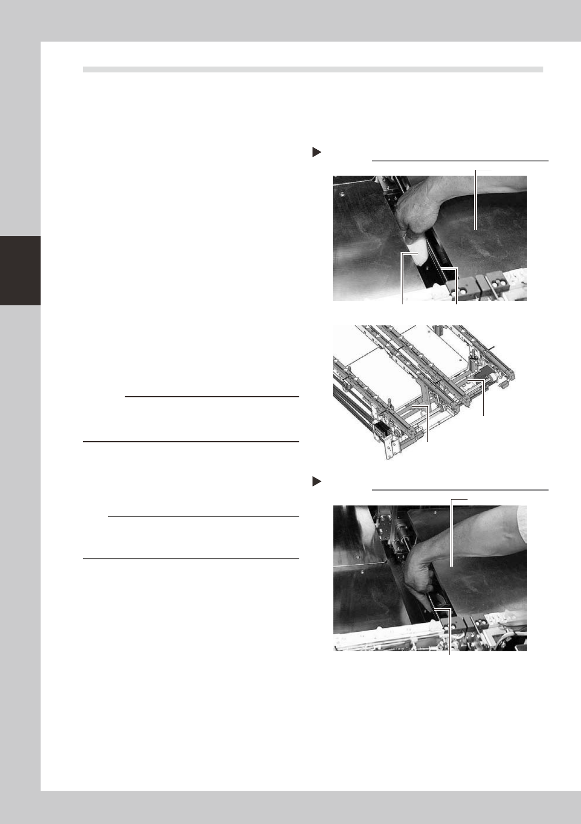
Clean the ball screw.
1. Set the board width to its maximum with
manual operation and then press the
emergency stop button. In the case of
dual-stage machines, raise the stage 1
and then press the emergency stop
button.
e
2. Wipe away the old grease and dirt from
the entire ball screw with a lint-free cloth
or paper towel (for clean room).
3. Cancel the emergency stop and make
the board width narrower. After that,
wipe also the remaining portions.
53384-L2-10
c
Carefully wipe the lead grooves of the ball screw during
is not produced.
3
Apply grease.
Apply the specified grease (NSL) by hand
uniformly over the surface and lead grooves
of the ball screw.
n
NOTE
In the same manner as described in step 2, adjust the
board width and apply the grease to the entire ball
screw.
53385-L2-00
Applying grease
Step 3
Stage 1
Grease
Cleaning the ball screw
Step 2
Dual-stage
Dual-lane
Cleaning cloth
W1-axis ball screw
W1-axis Ball screw
W2-axis Ball screw
Stage 1