YS24 保养手册.pdf - 第18页
3-16 3 Periodic maintenance items 3.1.1 Checking the ejector vacuum pressure Check the v acuum level of each ejector of the ejector unit to see if it is working correctly . e 1 Pr ess the emergency stop button. The machi…
3-15
3
Periodic maintenance items
3. Three-month inspection
3.1 Cleaning and replacing the ejector filter
Although depending on the air supply conditions and operating time, ejectors should be inspected once every
3 months. Use an air blow tool to remove dust buildups when small. We recommend replacing the air filter if
heavy dust deposits are found.
e
1
Make the preparations for the
cleaning and replacing work.
1. Take off all accessories susceptible to the
magnetic fields, such as a wristwatch
and/or magnetic ID card.
2. Press the emergency stop button to put
the machine in the emergency stop
state.
3. Put square bandages on the Y-axis linear
guide and push-up plate.
2
Remove the baffle plate.
Remove the baffle plate using the hex
wrench.
3
Remove the filter cap.
Loosen and remove the filter cap with a
slotted screwdriver.
53340-L2-00
4
Clean the filter.
Use tweezers to take the filter out of the
ejector. When there is only a little dust in the
filter, use an air blow tool to blow it away
and return the filter back to the original
position.
53316-L2-00
n
NOTE
If there are heavy dust deposits in the filter or the filter
has discolored, replace it with a new filter (K46-M8527-
C0X). As a general guide, filters should be replaced
once every 3 months, although this depends on the
actual operating time.
5
Reattach the filter cap.
1. Fit the filter into the filter cap and insert it
into the ejector.
2. Turn the filter cap to the right until it locks
and clicks.
c
6
Reattach the baffle plate.
Reattach the baffle plate at its original
position using the hex wrench.
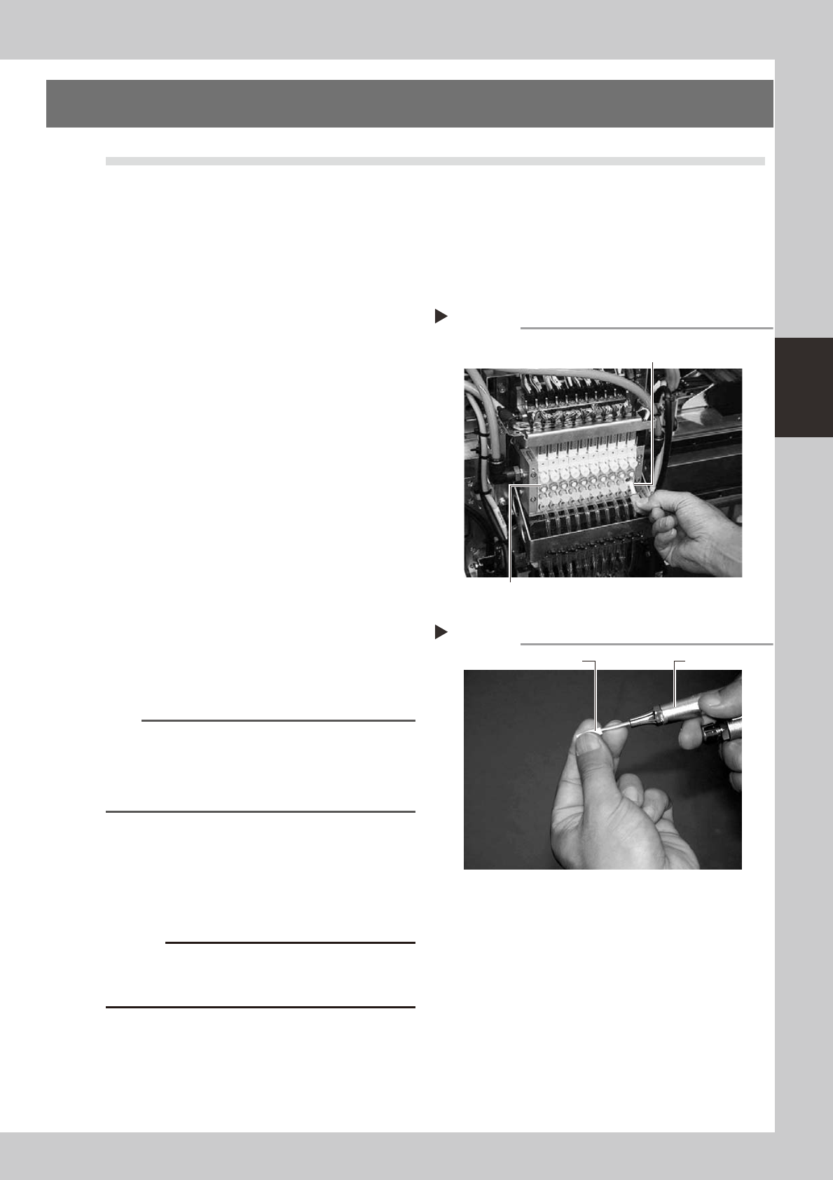
Removing the filter cap
Step 3
Ejector unit
Ejector filter
Filter cap, O-ring
Cleaning the filter
Step 4
Air blow toolFilter
3-16
3
Periodic maintenance items
3.1.1 Checking the ejector vacuum pressure
Check the vacuum level of each ejector of the ejector unit to see if it is working correctly.
e
1
Press the emergency stop button.
The machine should be in emergency stop
to ensure safety during work.
2
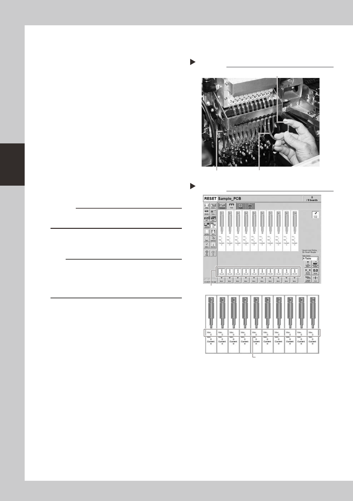
Disconnect the air hoses.
Disconnect all air hoses from the air joints at
the lower portion of the bearing holder.
53333-L2-00
3
Check the ejector vacuum level.
1. Open the [Unit]-[Head] tab.
2. Press the [Vacuum] button while blocking
each air hose with your finger.
3. Make a note of the "Max" reading of
each head while the air hose is blocked,
and check that the reading is higher
than the criterion value below.
Make the same check for all heads.
54305-L2-00
c
to wear safety goggles.
n
Criterion of ejector vacuum level
When air joint is blocked: 190 or more
TIP
If the vacuum level of any head does not reach the
criterion value, then check the air path in the head
(interior of the spline shaft or air hose between the
ejector and spline shaft). Clean or replace it if
necessary.
Disconnecting the air hoses
Step 2, 3
Air hose disconnected (transparent hose)
Block the air hose with your finger during measurement.
Bearing holder
Checking the vacuum levels
Step 3
Press the [Vacuum] button for each head.
Check "Max" vacuum levels
(with air joint blocked).
3-17
3
Periodic maintenance items
3.1.2 Checking the blow valve operation (each head)
Check the blow level of each ejector of the ejector unit to see if it is working correctly.
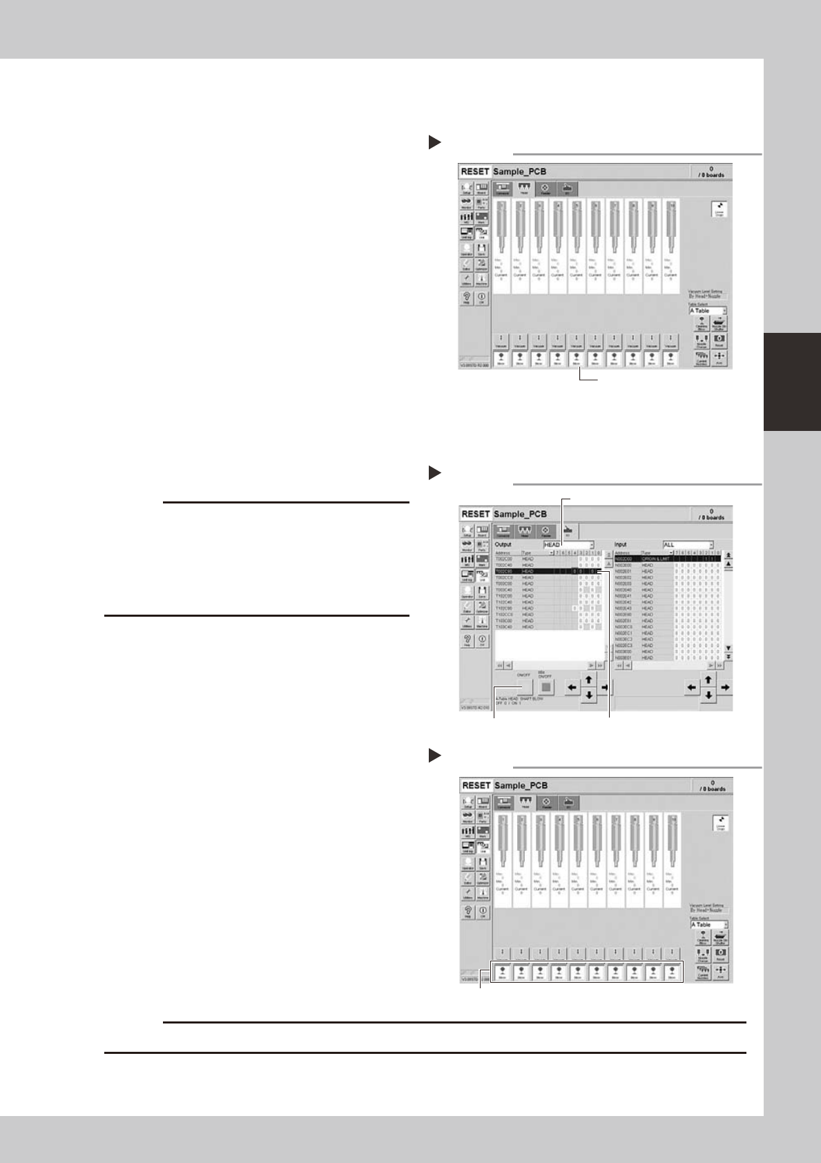
1
Check that the blow air is being
exhausted correctly.
To check if the blow air is being uniformly
exhausted from each air joint on the lower
part of the ejector unit, open the [Unit]-
[Head] tab and press the [Blow] button for
each head.
54307-L2-00
3.1.3 Checking the cleaning blow valve operation (for all heads)
Check that the cleaning blow function for the spline shafts is working correctly.
1
Remove the nozzles from all heads.
c
A strong air flow is exhausted during the cleaning blow.
Always remove all nozzles attached to the heads
before starting the cleaning blow. Starting the cleaning
blow while the nozzles are still attached may blow the
nozzles away from the heads causing the nozzles to
break or become lost.
2
Operate the cleaning blow valves.
1. Open the [Unit]-[I/O] tab.
2. Select [Head] from the Output dropdown
list and select an appropriate address for
the head shaft blow.
A-table: T002C804
B-table: T102C804
3. Press the [ON/OFF] button
to operate the
cleaning blow valves of all heads.
Change the address and operate the
blow valves for all tables.
54313-L2-00
3
Check the exhaust blow air of each
head.
Open the [Unit]-[Head] tab. Press the [Blow]
button of each head to check the exhaust
blow air from each head.
54308-L2-00
4
Turn OFF the cleaning blow valves.
c
Checking the exhaust blow air
Step 3
Press the [Blow] button for each head.
Operating the cleaning blow valves.
Step 2
Press the [ON/OFF] button. Select an address.
Select a head.
Checking the negative pressure
[Blow] button
Step 1