X-S Speicification.pdf - 第16页
16 Placement Heads SIPLACE SpeedStar (C&P20) SIPLACE S peedSt a r component camera type 23 (C&P20) SIPLACE S peedSt a r component camera type 41 (C&P20) Component range a a) Please note that the placeable com…
15
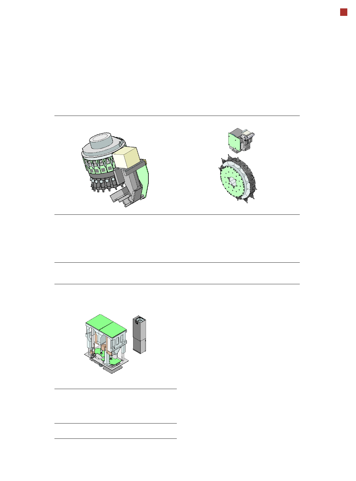
Placement Heads
Standard Functions / Options
SIPLACE SpeedStar (C&P20) SIPLACE MultiStar (CPP)
Standard-
functions
High-resolution camera, vacuum
sensor, force measurement,
component sensor, integrated
turning station per segment,
PCB warpage check, individual
image of each component
Standard-
functions
High-resolution camera, vac-
uum sensor, force measure-
ment, component sensor,
integrated turning station per
segment, PCB warpage check,
individual image of each com-
ponent
Options Nozzle changer, special nozzles Options Nozzle changer, special noz-
zles, stationary fine-pitch cam-
era
SIPLACE TwinStar (TH)
Standard-
functions
Stationary fine pitch camera,
vacuum sensor, force measure-
ment, nozzle changer, PCB war-
page check, individual image of
each component
Options Stationary flip chip camera, spe-
cial nozzles, grippers
16
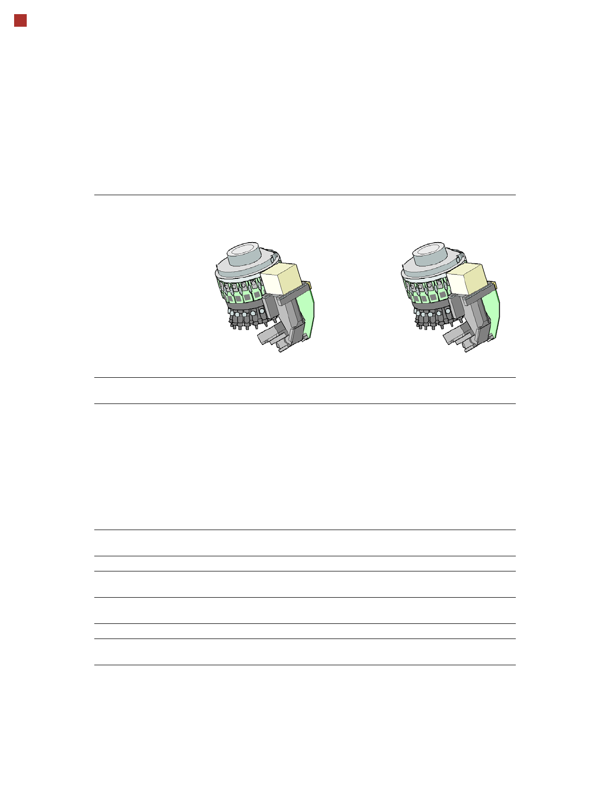
Placement Heads
SIPLACE SpeedStar (C&P20)
SIPLACE SpeedStar
component camera type 23
(C&P20)
SIPLACE SpeedStar
component camera type 41
(C&P20)
Component range
a
a) Please note that the placeable component range is also affected by the pad geometry, the customer-spe-
cific standards, the component packaging tolerances and the component tolerances.
01005 to 2220, Melf, SOT,
SOD
01005 to 2220, Melf, SOT,
SOD, Bare-Die, Flip-Chip
Component spec.
max. height
min. lead pitch
min. lead width
min. ball pitch
min. ball diameter
min. dimensions
max. dimensions
max. weight
4 mm
0.25 mm
0.1 mm
0.4 mm
0.2 mm
0.4 mm x 0.2 mm
6 mm x 6 mm
1 g
4 mm
0.08 mm
0.03 mm
0.10 mm
0.05 mm
0.12 mm x 0.12 mm
6 mm x 6 mm
1 g
Programmable set-down
force
1.5 N - 4.5 N 1.5 N - 4.5 N
Nozzle types 10xx, 11xx, 12xx 10xx, 11xx, 12xx
X/Y accuracy
b
b) The accuracy value, measured using the vendor-neutral IPC standard.
± 41 µm/3
± 55 µm/4
± 41 µm/3
± 55 µm/4
Angular accuracy ± 0.5° / 3
± 0.7° / 4
± 0.5° / 3
± 0.7° / 4
Illumination level 5 5
Possible illumination
level settings
256
5
256
5
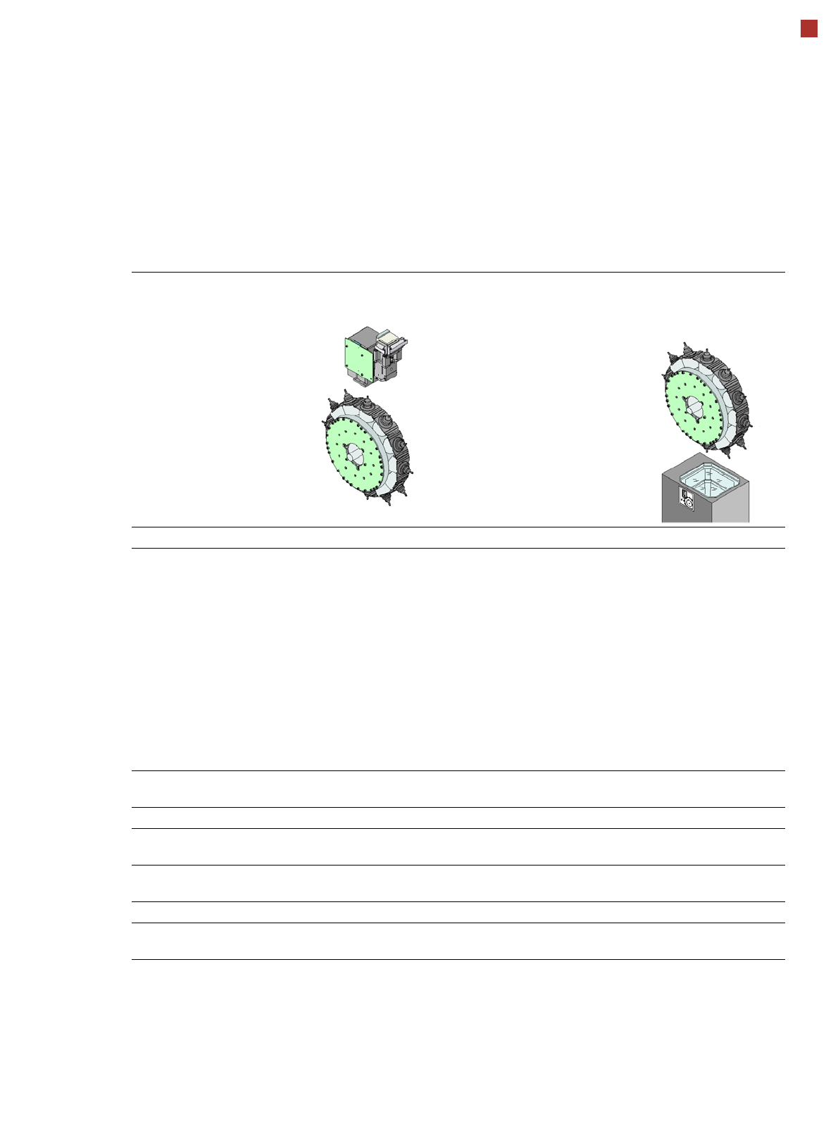
17
Placement Heads
SIPLACE MultiStar (CPP)
SIPLACE MultiStar
component-camera type 30
(CPP)
SIPLACE MultiStar
Component camera type
33
(CPP)
Component range
a
a) Please note that the placeable component range is also affected by the pad geometry, the customer-specific standards,
the component packaging tolerances and the component tolerances.
01005 to 27 mm x 27 mm 0402 to 50 mm x 40 mm
Component specification
Max.height
b
Max. height
c
Min. lead pitch
Min. lead width
Min. ball pitch
Min. ball diameter
Min. dimensions
Max. dimensions
Max. weight
b) CPP head: in low installation position (stationary component camera not possible).
c) CPP head: in high installation position
6.0 mm
8.5 mm
0.3 mm
0.15 mm
0.25 mm
d
0.35 mm
e
0.14 mm
d
0.20 mm
e
0.4 mm x 0.2 mm
27 mm x 27 mm
4 g
d) For components < 18 mm x 18 mm
e) For components ≥ 18 mm x18 mm
11.5 mm
0.3 mm
0.15 mm
0.35 mm
0.2 mm
1.0 mm x 0.5 mm
50 mm x 40 mm
8 g
Programmable set-down
force
1.0 - 10 N 1.0 - 10 N
Nozzle types 20xx, 28xx 20xx, 28xx
X/Y accuracy
f
f) The accuracy value, measured using the vendor-neutral IPC standard.
± 41 µm/3
± 55 µm/4
± 34 µm/3
± 45 µm/4
Angular accuracy ± 0.4° / 3
g
, ± 0.5° / 3
h
± 0.5° / 4
g
, ± 0.7° / 4
h
g) Component dimensions between 6 mm x 6 mm and 27 mm x 27 mm.
h) Component dimensions smaller than 6 mm x 6 mm.
± 0.2° / 3
± 0.3° / 4
Illumination level 5 6
Possible illumination
level settings
256
5
256
6