X-S Speicification.pdf - 第28页
28 PCB Warpage PCB warpage during placement PCB warpage downwards max. 0.5 mm Use the magnetic pin supports, to achieve this value. When there is warpage under 2 mm, the inkspots in the center of the board a re also with…
27
PCB Warpage
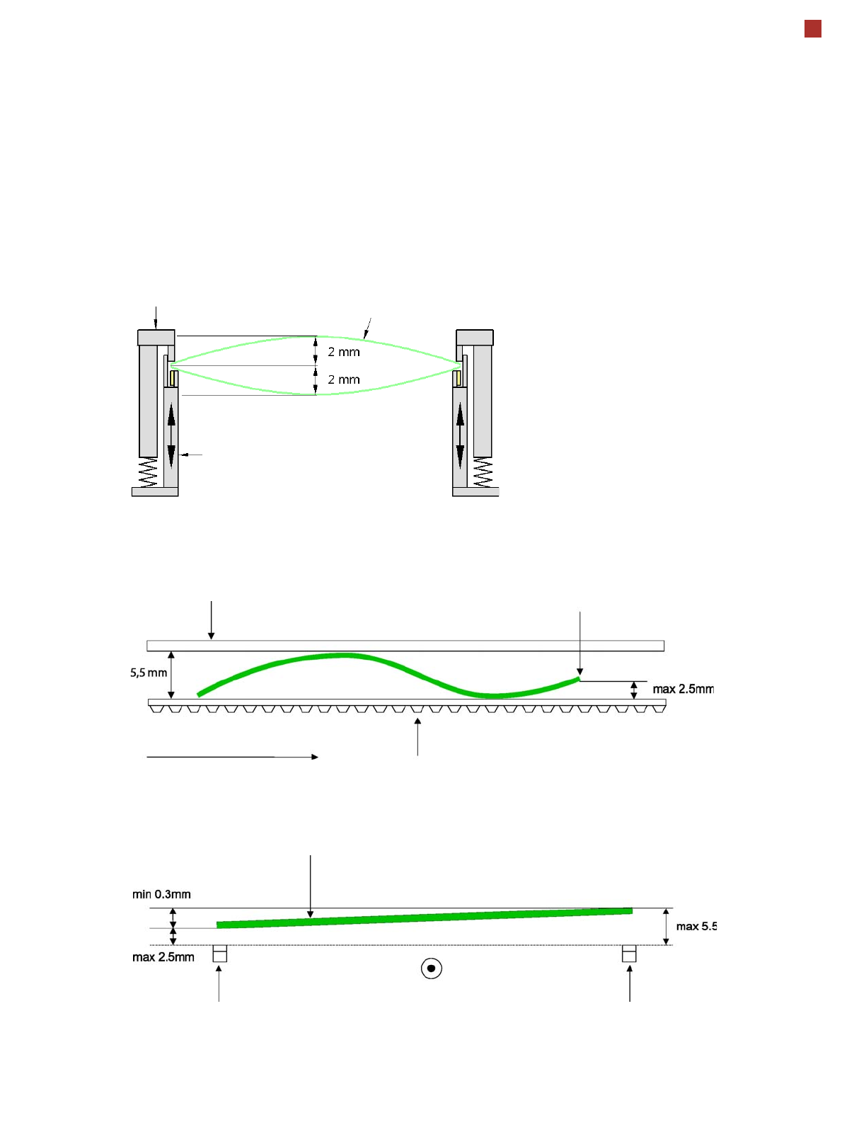
PCB warpage across the direction of travel
max. 1 % of the PCB diagonal, but not
exceeding 2 mm
PCB warpage on the conveyor
Fixed clamped edge
Movable clamping device
PCB
Fixed clamped edge
Conveyor belt
PCB transport direction
Front board edge
Front board edge
PCB warpage in direction of travel + PCB thickness < 5.5 mm
Bending up of front board edge max. 2.5 mm
Left conveyor belt
Right conveyor belt
PCB transport direction
28
PCB Warpage
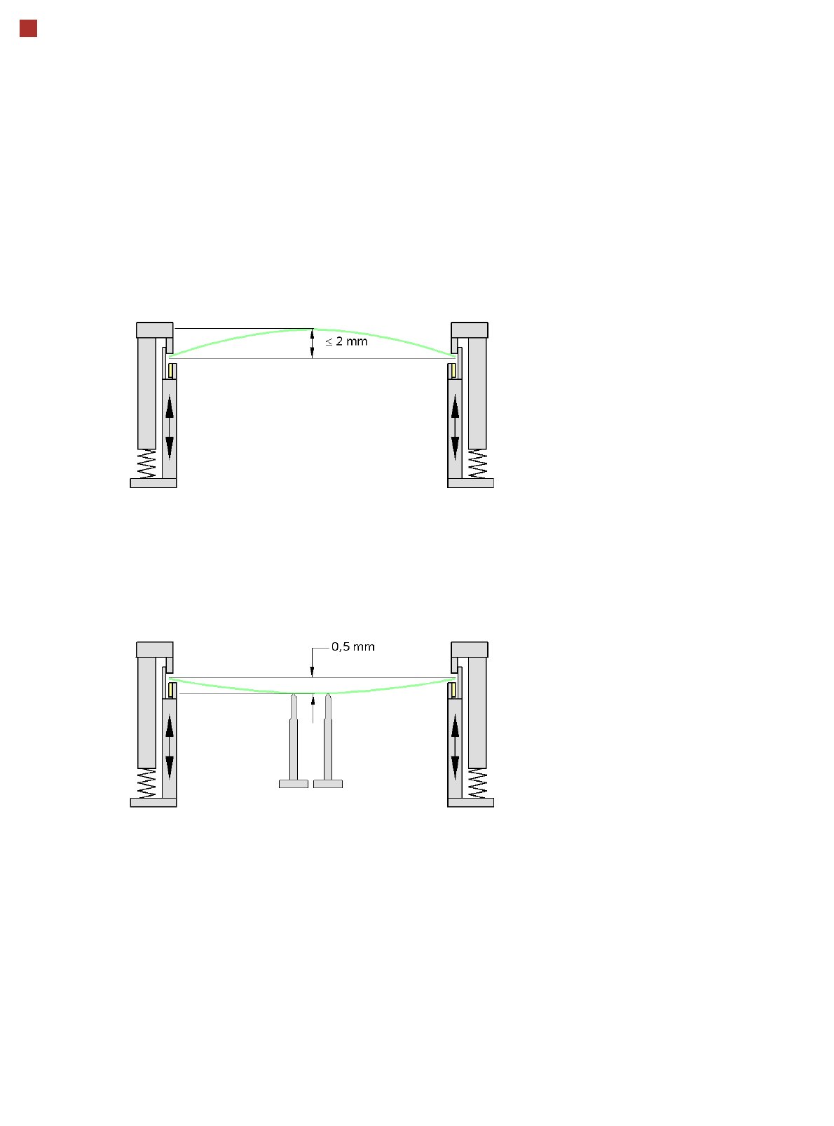
PCB warpage during placement
PCB warpage downwards max. 0.5 mm
Use the magnetic pin supports, to achieve
this value.
When there is warpage under 2 mm, the
inkspots in the center of the board are also
within the focus of the digital camera. When
all the tolerances are taken into account,
this value is reduced to 1.5 mm.
You should also note that the warpage
reduces the component height.
Magnetic pin support
29
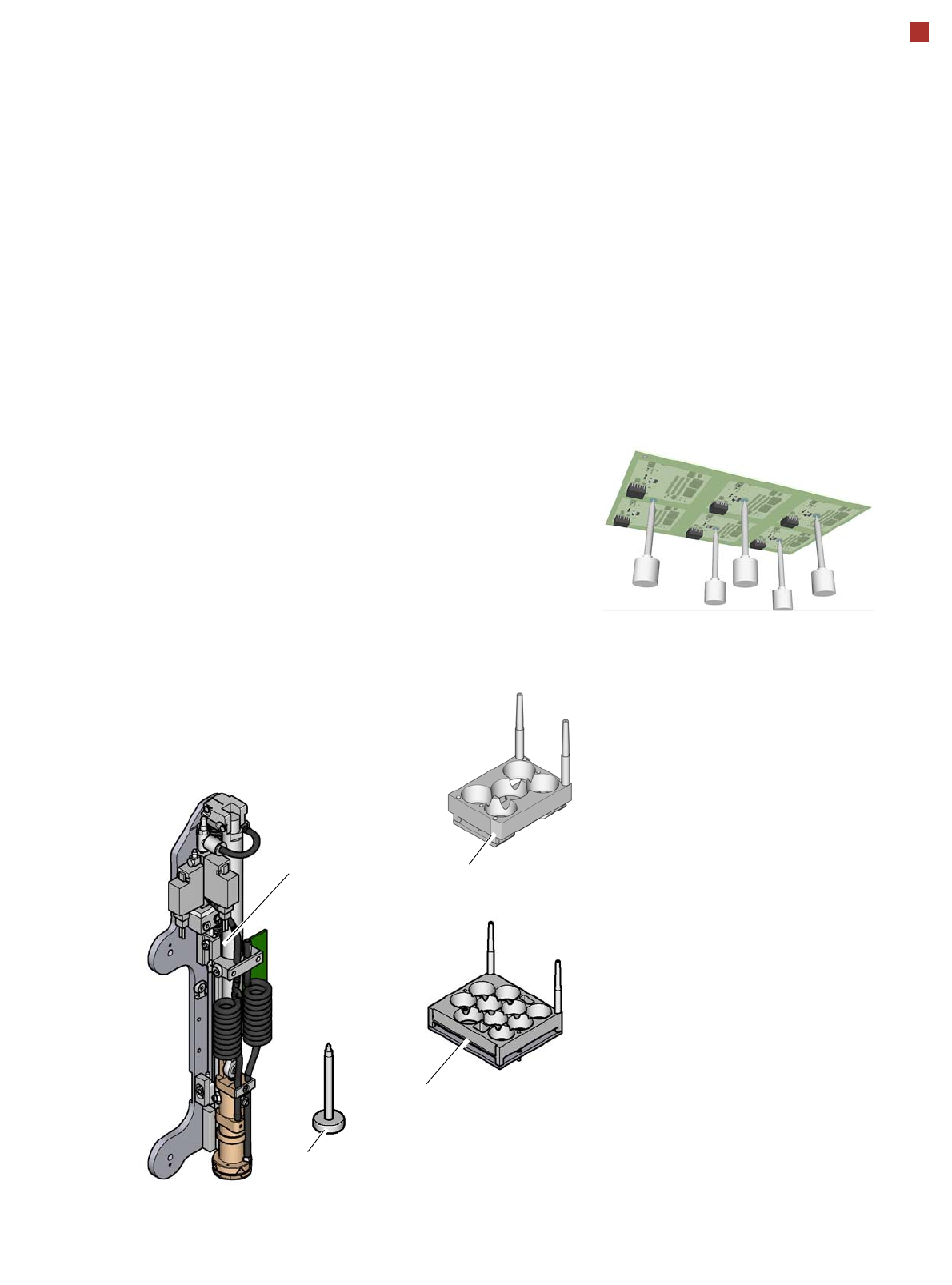
Smart Pin Support
Magazine W5
Magazine Q 10
General
Wide boards tend to deflect
during placement such that,
under certain circumstances,
the components can no lon-
ger be placed with the
desired accuracy. Highly
curved PCBs also affect the
placement accuracy. This
problem can be easily recti-
fied by fitting support pins on
the lifting table.
Smart Pin Support
The support pins are auto-
matically placed on the lifting
table with the help of the
Smart Pin Support option. A
gripper unit is used to pick
the support pins up from spe-
cial magazines and place
them in the prescribed posi-
tions.
Before a smart support pin is
placed, the position is
cleaned of any contaminants
with a gentle blast of air. In
addition, the correct position-
ing of the support pin is
checked after its placement,
with the PCB camera.
Magazine
There are two different mag-
azines available for auto-
matic changeover of max. 5
or max. 10 support pins in the
various machine configura-
tions. These magazines are
fixed to a magazine holder
and are fitted to the compo-
nent trolley docking unit.
Programming
The positions of the support
pins in the machine can be
defined for each board side,
in the SIPLACE Pro Board
Editor.
A 3D image of the board and
the support pins allows you
to recognize and prevent any
collision risks between the
support pin and the compo-
nents, even for stepped
transportation of boards with
excess length.
Gripper unit
Support pin