X-S Speicification.pdf - 第22页
22 Placement Heads Nozzle Changer Technical Data Nozzle changer for the SIPLACE MultiSt ar in the SIPLACE X4i S Dimensions (length x width x height) 314 mm x 94.5 mm x 68.6 mm Number of magazines a Location 1 and 3: b Lo…

21
Placement Heads
Nozzle Changer
Technical Data
Nozzle changer for the SIPLACE SpeedStar in the SIPLACE X3 S/X4 S
Dimensions (length x width x height) 449 mm x 94.5 mm x 79 mm
Number of magazines
a
Location 1 and 3:
b
Location 2 and 4:
a) All magazines in the nozzle changer must be configured.
b) For MTC with restrictions
6
6
Number of nozzle holders
Location 1 and 3:
Location 2 and 4:
72
72
Standard configuration 6 magazines with 72 nozzle garages
Option: Nozzle changer "row 2" 4 magazines with 48 nozzle garages
Nozzle types 10xx, 11xx, 12xx
Compressed air connection 0.45 MPa (4.5 bar)
Nozzle changer for the SIPLACE SpeedStar in the SIPLACE X4i S
Dimensions (length x width x height)
314 mm x 94.5 mm x 68.6 mm
Number of magazines
a
Location 1 and 3:
Location 2
b
and 4:
4
4
Number of nozzle holders
Location 1 and 3:
Location 2 and 4:
48
48
Standard configuration 4 magazines with 48 nozzle garages
Option: Nozzle changer "row 2" 4 magazines with 48 nozzle garages
Nozzle types 10xx, 11xx, 12xx
Compressed air connection 0.45 MPa (4.5 bar)
Nozzle changer for the SIPLACE MultiStar in the SIPLACE X3 S/X4 S
Dimensions (length x width x height) 449 mm x 62.7 mm x 77.7 mm
Number of magazines
a
Location 1 and 3:
Location 2
b
and 4:
6
6
Number of nozzle holders
Location 1 and 3:
Location 2 and 4:
72
72
Standard configuration 5 magazines with 60 x 20xx nozzle garages
1 magazine with 9 x 28xx nozzle garages
Option: Nozzle changer "row 2" 4 magazines

22
Placement Heads
Nozzle Changer
Technical Data
Nozzle changer for the SIPLACE MultiStar in the SIPLACE X4i S
Dimensions (length x width x height) 314 mm x 94.5 mm x 68.6 mm
Number of magazines
a
Location 1 and 3:
b
Location 2 and 4:
a) All magazines in the nozzle changer must be configured.
b) For MTC with restrictions
4
4
Number of nozzle holders
Location 1 and 3:
Location 2
b
and 4:
48
48
Standard configuration 3 magazines with 36 x 20xx nozzle garages
1 magazine with 9 x 28xx nozzle garages
Option:Nozzle changer "row 2" 4 magazines
Nozzle changer for the SIPLACE TwinStar
Dimensions (length x width x height) 448 mm x 68.5 mm x 49 mm
Number of magazines
a
Locations 1 and 3
Location 2 and 4
b
max. 12 magazines for max. 24 nozzle garages
max. 10 magazines for max. 20 nozzle garages
Number of nozzle holders may be freely configured
Standard configuration 3 magazines with two nozzle garages each
1 magazine with one nozzle garage
Nozzle types 4xx with adapter
5xx (standard)
9xx with adapter
Special nozzle, gripper
23
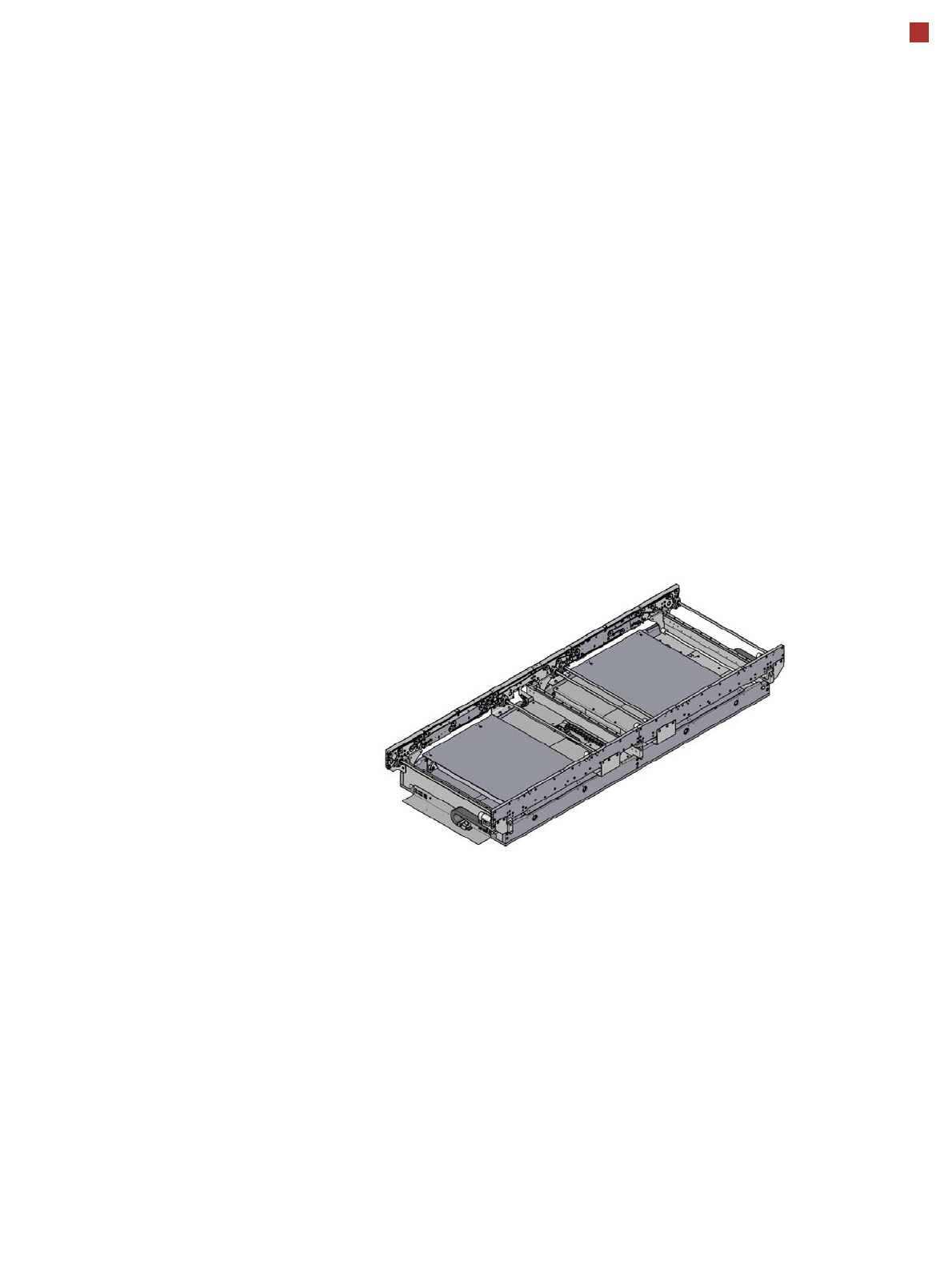
Board Conveyor
Single Conveyor
Conveyor transport princi-
ple
When the board reaches the
placement area, it is gently
slowed down (braked). As
soon as the board has
reached its target position,
the conveyor belt is stopped
and the board is clamped
from below. The placement
process begins immediately
afterwards. The transporta-
tion and clamping of the
boards is monitored.
Position of conveyor sides
The conveyor can be easily
adjusted with the automatic
electrical width adjustment
system, to accommodate
various different board
widths. Both the single and
flexible dual conveyor allow
you to set the fixed conveyor
side on the right or left, as
required.
Alternating placement
mode
In the sophisticated
SIPLACE placement con-
cept, the two heads operate
alternately to process boards
on both conveyor lanes.
While the first head places
components on both boards,
the other head picks up new
components.
Single conveyor
When using a single con-
veyor, boards are moved
behind one another, along a
conveyor lane and into the
placement machine, where
they are placed. This con-
veyor variant is particularly
suitable for very wide boards.
Single conveyor