00198374-01_UG_OSC_Package_DE_EN.pdf - 第48页
3 Prerequisites 3.2 Hardware requirements 48 Bedienungsanleitung OSC Package User Guide OSC-Paket - 06/2017
3 Prerequisites
3.1 Software Requirements
Bedienungsanleitung OSC Package User Guide OSC-Paket - 06/2017 47
3 Prerequisites
The necessary system requirements for the OSC package correspond to the system requirements
for SIPLACE Pro and are described in the SIPLACE Pro Version Description,
item no. [00198238-xx] .
3.1 Software Requirements
●
SIPLACE Pro from Version 14.0 (R16-2)
●
Station software from Version 710.0 (R16-2)
●
SIPLACE Vision from Version 5.4.1 (R16-2)
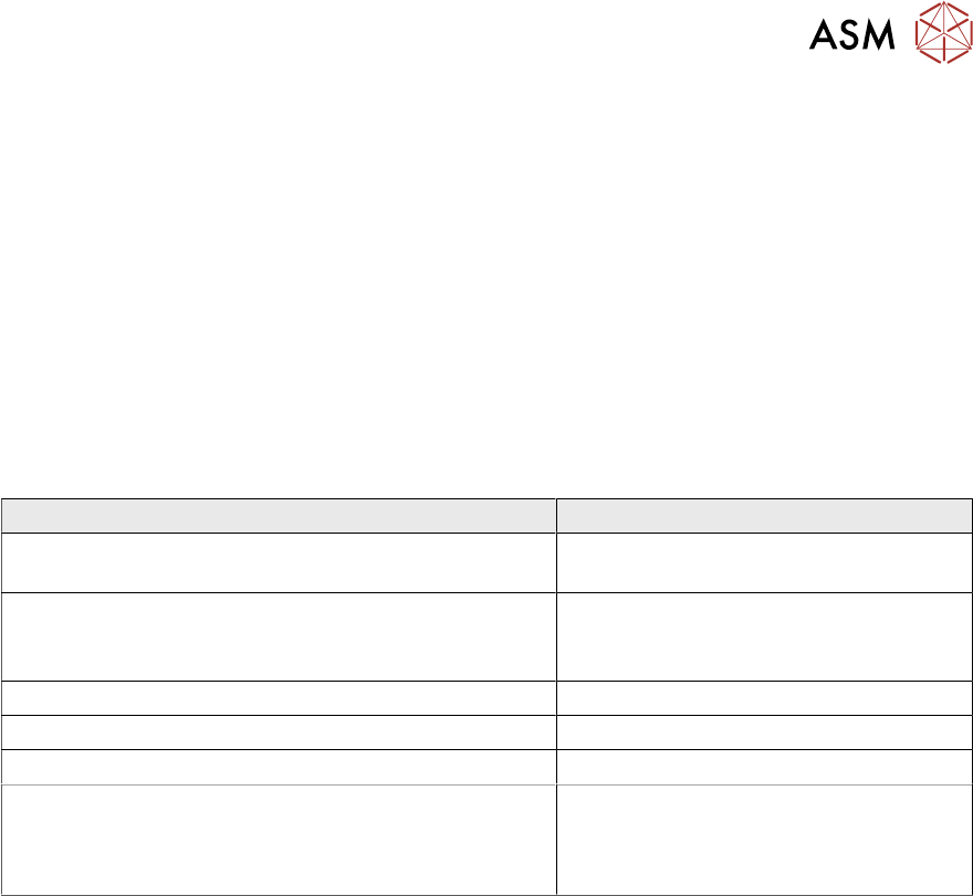
3.2 Hardware requirements
Function Hardware
Improved placement of snap-in components Placement head: VHF TH
Smart Pin Support is recommended
Stereo Measurement for THT Pins Placement heads: CPP, TH, HF TH,
VHF TH
Camera types: SST33, SST25
Customer-specific Pattern Features Placement heads: All
Special Position Evaluation Placement heads: All
Support to find best acceleration Placement heads: All
Increased placement force for VHF TH placement head
to 100 N
Placement head: VHF TH
Can only be used with function status
-03!
Smart Pin Support is recommended

3 Prerequisites
3.2 Hardware requirements
48 Bedienungsanleitung OSC Package User Guide OSC-Paket - 06/2017

4 Working with the OSC Features
4.1 Placement of Snap-In Components
Bedienungsanleitung OSC Package User Guide OSC-Paket - 06/2017 49
4 Working with the OSC Features
This chapter describes how to work with the single OSC features.
► Make use of the information provided in the Online Help files for SIPLACE Pro and the station
software. These files contain additional, detailed information about the OSC features.
4.1 Placement of Snap-In Components
When placing snap-in components, it must be ensured that the components lock correctly into the
board. The system can verify this by an improved method.
Example
Snap-in component
Snap-in component – not placed correctly
Snap-in component – placed correctly
The actual Z-axis position of every snap-in placement will be compared with its corresponding
height reference value during the verification. These values must match each other.
The snap-in placement process has to be enabled for the component shape in SIPLACE Pro.
Additionally, the snap-in threshold that shall be used for comparing the two values has to be
specified.