00198374-01_UG_OSC_Package_DE_EN.pdf - 第58页
4 Working with the OSC Features 4.2 Stereo Measurement for THT Pins 58 Bedienungsanleitung OSC Package User Guide OSC-Paket - 06/2017 Step 3: SIPLACE Pro Setting parameters for the nozzle gripper ► In the Nozzle Editor, …
4 Working with the OSC Features
4.2 Stereo Measurement for THT Pins
Bedienungsanleitung OSC Package User Guide OSC-Paket - 06/2017 57
4.2.2 Application Example
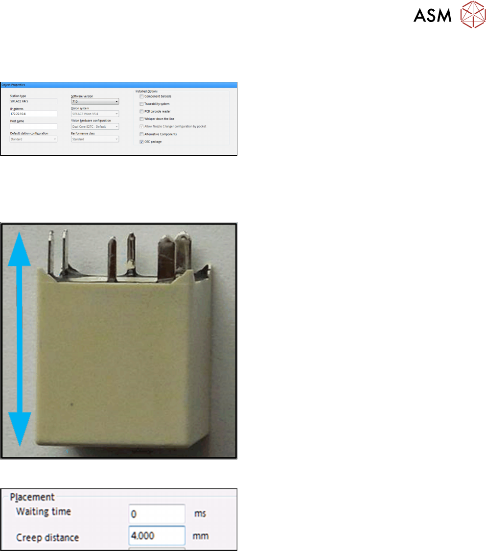
Step 1: SIPLACE Pro
► In the Station Editor under Placement Station,
enable the OSC Package option under Installed
options.
In SIPLACE Pro the component height has to be set so that the THT pin tips are located in the
focal plane of the camera. In the focal plane, the THT pin tips are displayed most sharply, and the
measurement is most accurate. There are two options to do this:
Step 2: First option – SIPLACE Pro
Setting the component overall height (from the pin tips
to the component bottom).
► In the Component Shape Editor, set the
component overall height under Component
Shape – Form – Overall height (with pins).
Step 2: Second option – SIPLACE Pro
Setting creep distance = THT pin length
► In SIPLACE Pro Desk, set the creep distance =
THT pin length under Handling – Placement –
Creep Distance.
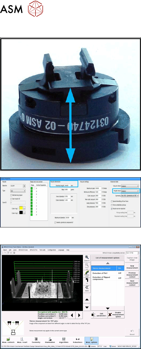
If you use a nozzle gripper, the nozzle height also has to be set.
4 Working with the OSC Features
4.2 Stereo Measurement for THT Pins
58 Bedienungsanleitung OSC Package User Guide OSC-Paket - 06/2017
Step 3: SIPLACE Pro
Setting parameters for the nozzle gripper
► In the Nozzle Editor, disable the Height check
height reference run under Custom Nozzle –
Advanced Data.
► Set the Nominal length from the nozzle bottom to
the component touchdown point under Nozzle
dimensions.
Step 4: SIPLACE Vision
► Enable the Stereo Measurement option in the
Component shape wizard in the Meas. options.
4 Working with the OSC Features
4.2 Stereo Measurement for THT Pins
Bedienungsanleitung OSC Package User Guide OSC-Paket - 06/2017 59
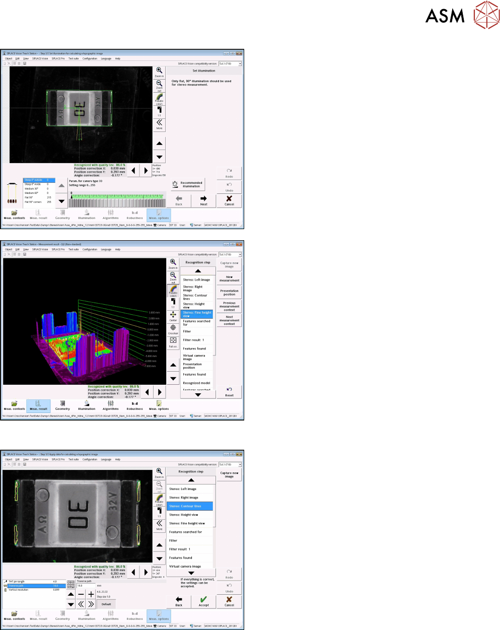
► With the Set illumination option you may check
the illumination setting.
Normally, the pre-set values should not be
changed!
► Under Stereo: Fine Height View you may check
the result of the stereo measurement.
Ensure that the THT pins are in the focal plane
(yellow height line)
This is the case, if component height (overall
height) and nozzle height have been defined
correctly.
Step 5: SIPLACE Vision
► If necessary, change the traverse path to modify
the vertical resolution.
► Under Stereo: Contour lines the measured height
lines are displayed in the 2D images.
This allows you to verify that exactly the THT pin
tips have been detected at the focal plane.