Queue-Inspection-Manual-REV-G-2.pdf - 第11页
Queue/In spectio n Revision G / January 2022 Page 11 of 21 Machine Communica tions (SMEMA) Fo r manufacturi ng lines (mu ltipl e machines u til izing conv eyor syste ms) SMEMA c ables are used so t he machines can commun…
Queue/Inspection
Revision G / January 2022
Page 10 of 21
Installation and Setup
WARNING: The following procedures should be done by qualified persons in
accordance with this manual and applicable safety regulations. A “qualified person” is
defined as “a person or persons who, by possession of a recognized degree or
certificate or professional training, or who, by extensive knowledge, training, and
experience, has successfully demonstrated the ability to solve problems relating to
the subject matter and work.” (ref. ANSI/ASME B30.2-1983.)
Unpacking and Inspection
1. Remove all packing materials and strapping. Thoroughly examine the machine for
damage, loose fasteners, etc.
2. Open the electrical enclosure and visually examine the connectors and components
for vibration during shipping.
3. Close the door.
Installation
1. Connect the machine into an appropriate power source. Refer to the legend plate on
the rear of the machine. The electrical service must be correctly grounded and the
power source “clean”. If high power equipment operates off the same source, a line
conditioner may be necessary. Poor quality power can cause machine errors.
WARNING: Failure to comply with electrical specifications can result in damage to the
machine as well as injury to installation personnel. Electrical hookup must be made by
a qualified electrician and must comply with any applicable local standards.
2. Close any access doors and engage the “Emergency Stop” button.
3. Set the main power switch to “On”.
Queue/Inspection
Revision G / January 2022
Page 11 of 21
Machine Communications (SMEMA)
For manufacturing lines (multiple machines utilizing conveyor systems) SMEMA cables are
used so the machines can communicate. The cables must be connected in the correct
manner.
Note: On the diagrams the J# refers to the label on the machine, not the label on the
cable.
The Surface Mount Equipment Manufacturers Association (SMEMA) Electrical Equipment
Interface Standard is used to make sure the boards sequence is correct. If these connections
are not correct, boards cannot move from one machine to another.
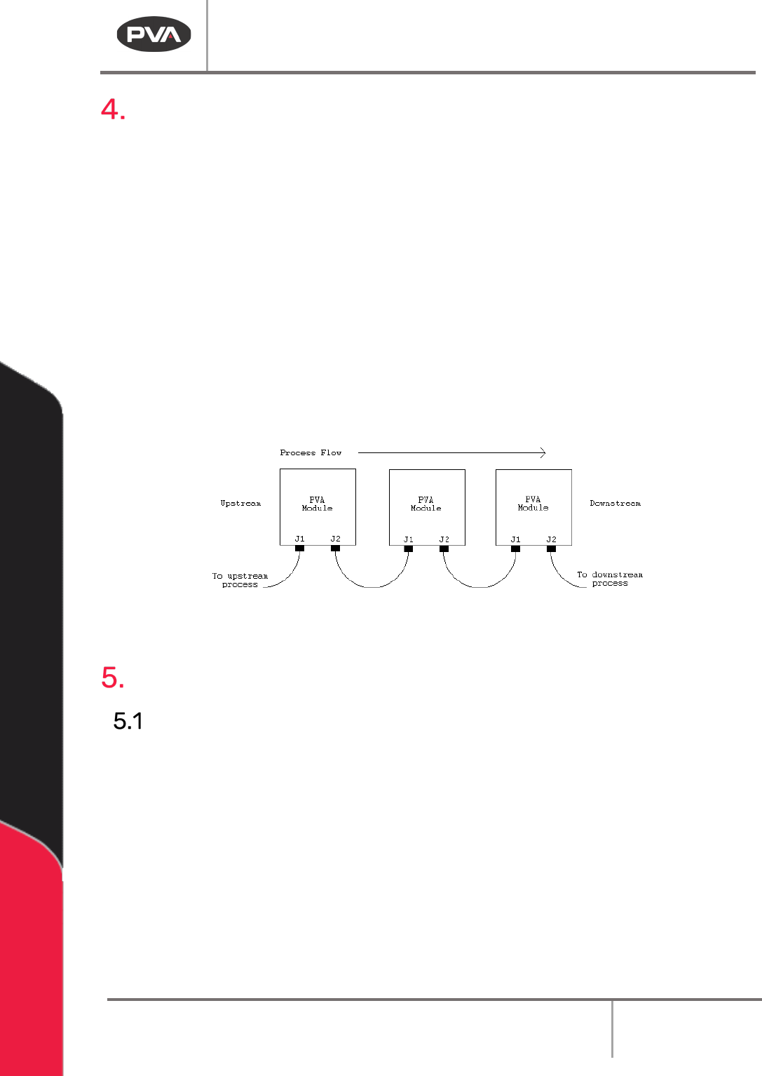
SMEMA cables have male 14-pin amp-type CPC connectors. The cables are straight-
through, so orientation does not matter. On each module, the wire to the J1 plug must
connect to the J2 plug on the machine upstream. Similarly, the J2 plug on each machine
must connect to the J1 plug on the machine downstream, as shown below:
Figure 2: SMEMA Connections
Operating Safety
Notices and Warnings
• Wear safety glasses, gloves, and long-sleeved clothing to operate automated
industrial equipment.
• Read and understand all operating manuals before using this equipment.
• Do not disable the safety features of the machine.
• Lock-out and tag the air and power supplies before servicing or cleaning any part of
this equipment.
• Relieve the pressure before you remove any hose.
• Use hoses with sufficient pressure ratings.
• Use replacement parts recommended or supplied by the manufacturer.
• Stay away from all moving parts when the system is in operation.
Queue/Inspection
Revision G / January 2022
Page 12 of 21
Safety Devices and Guarding
The PVA Queue/Inspection module has safety features that protect the operator from
hazards during normal operation of the machine.
Note: The safety features should NEVER be bypassed, disabled or tampered with.
Precision Valve and Automation is not responsible for any damages incurred,
mechanical or human, because of alteration or destruction of any safety features.
Safety Circuit
The 24 VDC power for the PVA Queue/Inspection module is monitored and controlled by the
safety circuit. The safety circuit has a control relay and Emergency Stop button. The control
relay stops power to the conveyor drive. The programmable logic controller (PLC) monitors
the status of the control relay. The PLC will stop operation of the machine if the relay opens.
Exhaust Requirements
Exhaust
Requirement
Machine Duct Size
Air Velocity at Test
Point (ft/min)
Air Velocity at Test
Point (m/sec)
300 CFM
4” (102mm)
3438
17.5
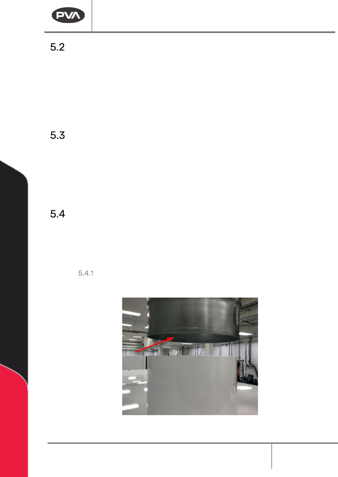
Air Velocity Test Point
Measure the velocity at the inlet to the factory supplied duct.
Figure 3: Air Velocity Test Point