Queue-Inspection-Manual-REV-G-2.pdf - 第18页
Queue/In spectio n Revision G / January 2022 Page 18 of 21 Fault Diagnosis Operation Other Sympto ms Possible C ause Corrective A ction Board doesn’t tran sfer to or f rom adjacen t station SMEMA connection is bro ken Ex…

Queue/Inspection
Revision G / January 2022
Page 17 of 21
Troubleshooting
Some problems are easy to identify and solve, for others more help may be necessary. This
section is to assist in solving problems before you seek additional help. Refer to this section
if a mechanical or electrical problem occurs.
Calling Technical Support
The technical support staff is always available to help solve any problems. The phone
number is +1-518-371-2684. Have the following information before calling for help:
• The operation in progress when the machine had trouble (when did it have problems,
what was it doing, etc.).
• If the error was not serious, attempt to repeat the error. If the error does not repeat,
the problem may have been operator generated.
Queue/Inspection
Revision G / January 2022
Page 18 of 21
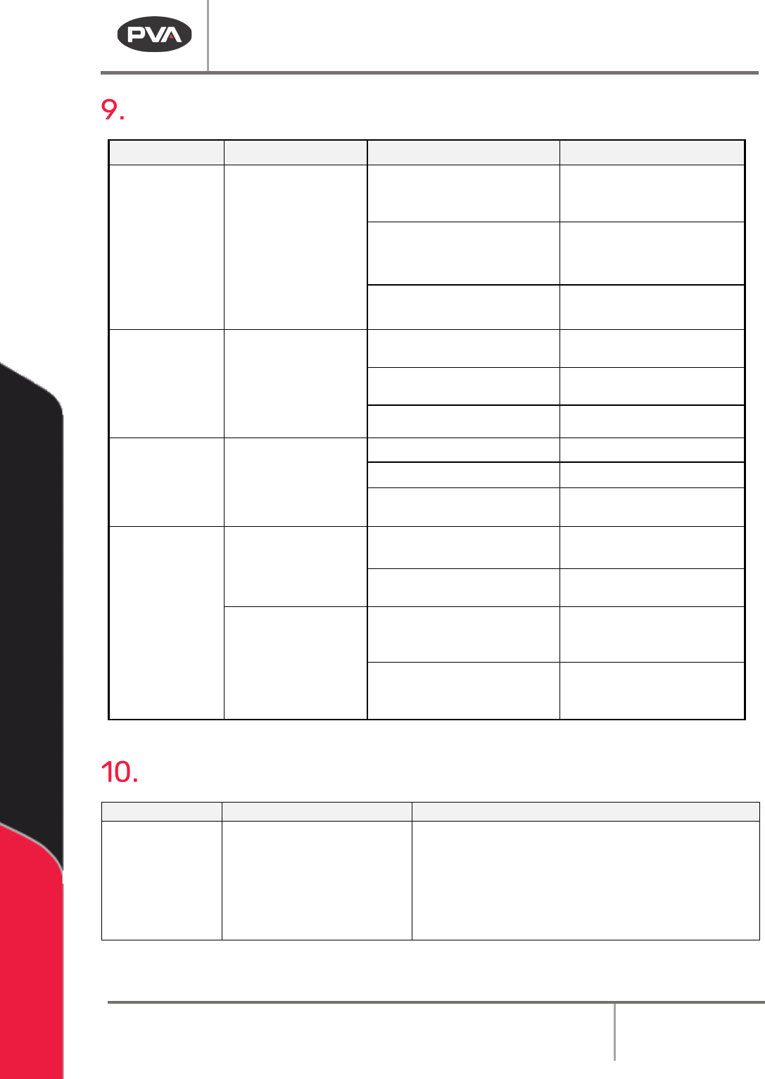
Fault Diagnosis
Operation Other Symptoms Possible Cause Corrective Action
Board doesn’t
transfer to or from
adjacent station
SMEMA connection is broken
Examine and correct the cable
connections
A module in the system is
turned off
Turn on the inactive module
The adjacent stations are not
correctly aligned
Align the adjacent stations
Part-in-place
sensor failure
Cable is loose or not connected
Examine and correct the cable
connections
The sensor is not positioned
correctly
Move the sensor
The sensor is dirty or scratched
Clean or replace the sensor
Pneumatic
position failure
The air lines are kinked or torn
Repair or replace the lines
Position sensor failure Replace the sensor
Position sensor needs to be
adjusted
Move the sensor
Conveyor does not
run or another
conveyor error
The conveyor belt is stuck to
the rails
Clean the rails or replace the
belt
Cable is loose or not connected
Examine and correct the cable
connections
There is no power to
the conveyor motor
Control relay not energized or
Power On light not illuminated
(Certain Models)
Examine voltages and
connections
The fuse is blown Correct or replace FU-3 in
the
electrical enclosure if
necessary
Maintenance
Service Area
Weekly
Monthly
Conveyor System
Belts
Examine the sensors for
material and buildup
• Examine the conveyor belts for wear
• Conveyor System Chains: Lubricates chain with
Darmex 773ND or equivalent
• Conveyor System Rails: Clean and lubricate
with Mobile DTE-24 or equivalent. You can also
use Darmex 773ND or equivalent.

Queue/Inspection
Revision G / January 2022
Page 19 of 21
Conveyor Belt Replacement
1. Disconnect, lockout and tag the power supply.
2. Use a 3 mm hex key to remove the dust cover plate. The dust cover plate is near the
conveyor motor on the inside of the conveyor.
3. Use your hands to remove the old conveyor belt from the pulley wheels.
4. Install the new conveyor belt. Put the belt on the pulley wheels farthest from the
motor first.
Note: Make sure that there are no twists in the belt.
5. Put the belt around the large pulley wheel, then around the remaining wheels.
6. Use your hands to turn the pulley wheels several turns by hand to make sure the belt
is correctly installed.
7. Use a 3 mm hex key to install the dust cover plate.
Conveyor Speed
The conveyor speed is controlled by increasing or decreasing the line voltage to the stepper
driver with a potentiometer (R4). To adjust the conveyor speed, do the procedure below:
1. Open the enclosure access door.
2. In the enclosure, find the speed control potentiometer R4 in the top right corner.
3. Cause the upstream sensor to operate the conveyors.
4. Use a small flat blade screwdriver and turn the screw clockwise to decrease conveyor
speed, or counterclockwise to increase conveyor speed.
5. The factory setting for the conveyor speed is 80 ft/min. To go back to the factory
setting, do the steps above and adjust the speed until the voltage across the
terminals on the potentiometer R4 is 8 volts.