Queue-Inspection-Manual-REV-G-2.pdf - 第12页
Queue/In spectio n Revision G / January 2022 Page 12 of 21 Saf ety Dev ices and G uard ing Th e PVA Queue/I nsp ection module has saf ety featu res th at prot ect the op erator fr om hazards durin g normal ope ration of …
Queue/Inspection
Revision G / January 2022
Page 11 of 21
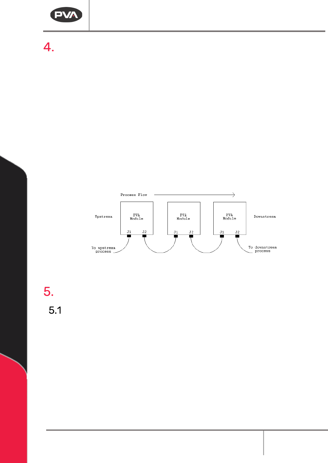
Machine Communications (SMEMA)
For manufacturing lines (multiple machines utilizing conveyor systems) SMEMA cables are
used so the machines can communicate. The cables must be connected in the correct
manner.
Note: On the diagrams the J# refers to the label on the machine, not the label on the
cable.
The Surface Mount Equipment Manufacturers Association (SMEMA) Electrical Equipment
Interface Standard is used to make sure the boards sequence is correct. If these connections
are not correct, boards cannot move from one machine to another.
SMEMA cables have male 14-pin amp-type CPC connectors. The cables are straight-
through, so orientation does not matter. On each module, the wire to the J1 plug must
connect to the J2 plug on the machine upstream. Similarly, the J2 plug on each machine
must connect to the J1 plug on the machine downstream, as shown below:
Figure 2: SMEMA Connections
Operating Safety
Notices and Warnings
• Wear safety glasses, gloves, and long-sleeved clothing to operate automated
industrial equipment.
• Read and understand all operating manuals before using this equipment.
• Do not disable the safety features of the machine.
• Lock-out and tag the air and power supplies before servicing or cleaning any part of
this equipment.
• Relieve the pressure before you remove any hose.
• Use hoses with sufficient pressure ratings.
• Use replacement parts recommended or supplied by the manufacturer.
• Stay away from all moving parts when the system is in operation.
Queue/Inspection
Revision G / January 2022
Page 12 of 21
Safety Devices and Guarding
The PVA Queue/Inspection module has safety features that protect the operator from
hazards during normal operation of the machine.
Note: The safety features should NEVER be bypassed, disabled or tampered with.
Precision Valve and Automation is not responsible for any damages incurred,
mechanical or human, because of alteration or destruction of any safety features.
Safety Circuit
The 24 VDC power for the PVA Queue/Inspection module is monitored and controlled by the
safety circuit. The safety circuit has a control relay and Emergency Stop button. The control
relay stops power to the conveyor drive. The programmable logic controller (PLC) monitors
the status of the control relay. The PLC will stop operation of the machine if the relay opens.
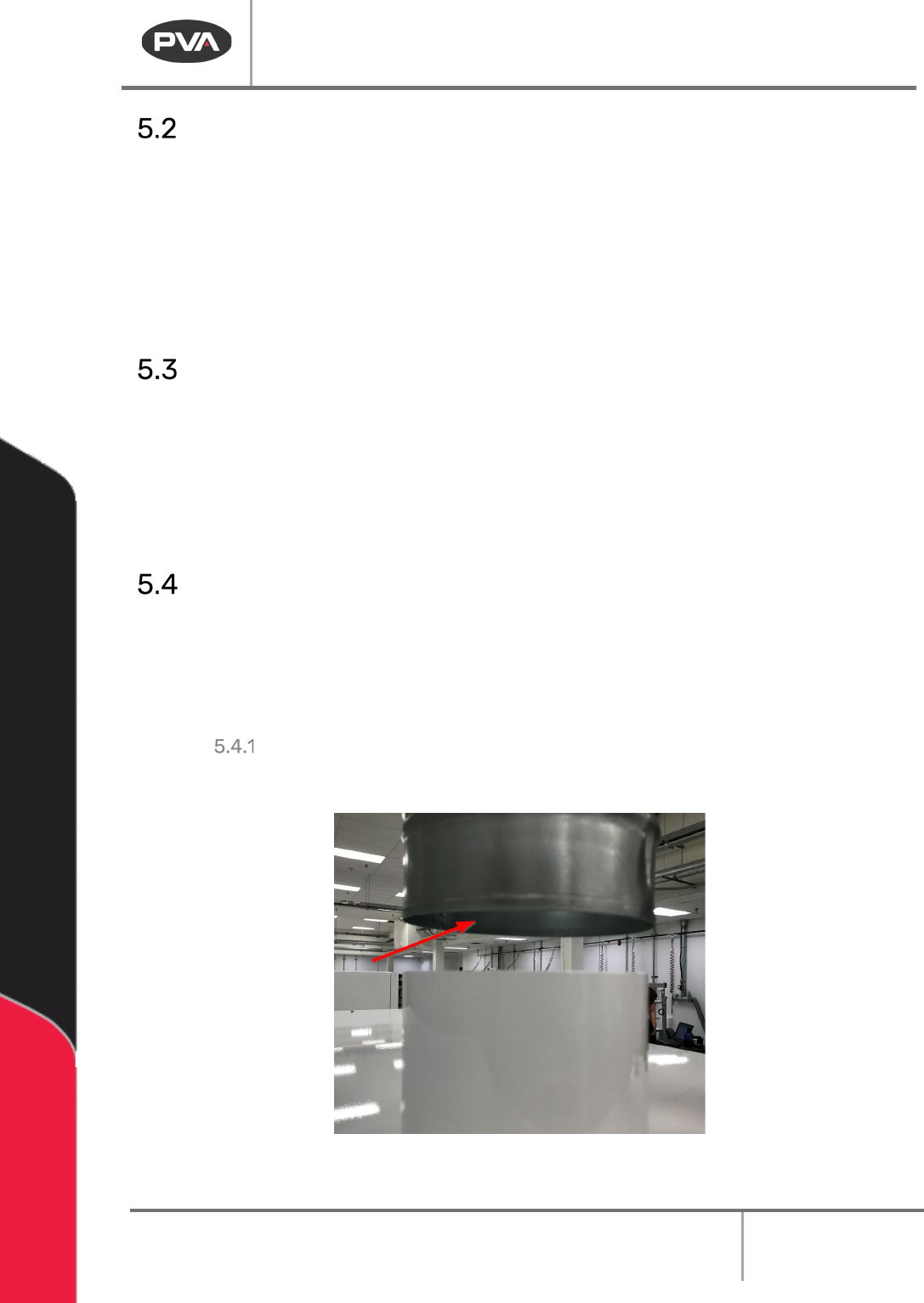
Exhaust Requirements
Exhaust
Requirement
Machine Duct Size
Air Velocity at Test
Point (ft/min)
Air Velocity at Test
Point (m/sec)
300 CFM
4” (102mm)
3438
17.5
Air Velocity Test Point
Measure the velocity at the inlet to the factory supplied duct.
Figure 3: Air Velocity Test Point
Queue/Inspection
Revision G / January 2022
Page 13 of 21
Operation
Startup Procedure
1. Engage the Emergency Stop button.
2. Set on the main power switch to “On”.
Light Tower Operation
Three stacked indicator lights and a buzzer are used to show the status of the machine. The
lights are green, amber, and red with the buzzer below the green light. The lights are visible
from all sides of the machine. The indicators operate as follows:
State
Red
Amber
Green
Buzzer
Cycle Stop
ON
OFF
OFF
OFF
Auto Cycle OFF OFF ON OFF
Cycle Stop OFF ON OFF OFF
Auto Cycle Standby OFF ON OFF OFF
Machine Error OFF OFF OFF Buzz
Figure 4: Light Tower and Buzzer Status
Shutdown Procedure
1. Wait for all boards to clear the module. The machine should be shutdown with no
parts in the module.
2. Set the main power switch to “Off”.
Caution: If maintenance will be done during the shutdown, lockout and tag the
machine.
Cycle Stop
Cycle stop state is the default state for the PVA Queue/Inspection module. Cycle stop occurs
when the Emergency Stop button is engaged and there is no fault. The red light will be on in
cycle stop. The machine will not cycle boards in this state. To enter auto cycle, disengage
the Emergency Stop button.