161页面.pdf - 第11页
T R o t ary Cam sw itch es - Ov e rv ie w Sys tem over view AUTO HAND O 1 0 2 9 3 4 4 4 5 6 6 6 7 7 8 1 9 TM - Control switches TM Switch-disconnectors 1 2 5 3 4 4 4 6 6 6 7 8 8 8 8 9 8 9 10 8 1. Flush mounting 2.Center …
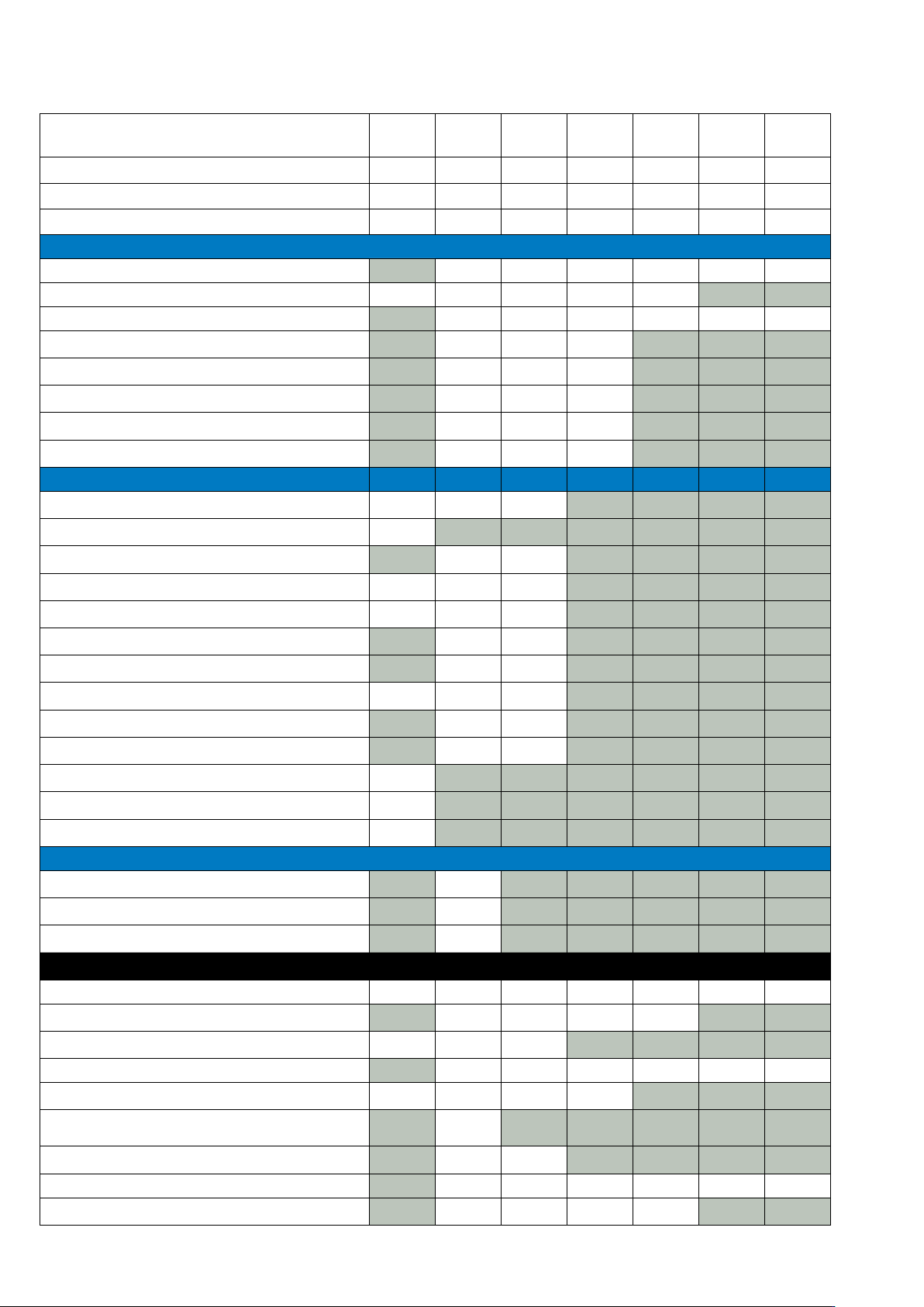
T Rotary Cam switches - Overview
TM T0 T3 T5B T5 T6 T8
Rated current (Amps) ≤10 20 32 63 100 160 315
Rated voltage (V a.c.) 500 V 690 V 690 V 690 V 690 V 690 V 690 V
Max motor rating AC-23A 400/415 V 50/60 Hz 3.0 kW 6.5 kW 13 kW 22 kW 30 kW 55 kW 132 kW
Switch-disconnectors
Main switches maintenance/manual override switches
On-Off switches
Changeover switches
Reversing switch with 0 position
Star-delta switches
Reversing star-delta switches
Multi-speed switch
Reversing multi-speed switches
Control switches
Step switches
Control circuit isolators
On-Off switches
Changeover switches
Manual/Auto switches
On switches
Universal control switches
Coding switches
Series switches
Instrument selector switches
Mini Cam Group switches
Mini Cam ON-OFF switches
Mini Cam Reversing switches
Switches with locking mechanism - Panic switch
With cylinder lock SVA
With padlocking feature SVC
On-Off switch without emergency stop function
Mounting forms
‘E’ Flush mounting
‘EA/SVB’ Flush mounting main switch
‘EZ’ Centre mounting
‘I’ Enclosed switch-disconnector fitted in Ci-K Enclosure
‘IVS’ Service distribution board mounting
‘MBS’ Enclosed switch-disconnector fitted in Ci-K Enclosure, with
pre-assembled EMC screen
‘SE’ Enclosed switch-disconnectors fitted in steel enclosures
‘V/SVB’ Rear mounting main switches
‘Z’ Rear mounting
Range overview by switch-disconnectors type and mounting forms
10
EATON P Switch-disconnectors and T Rotary cam switches CA042001EN
T Rotary Cam switches - Overview
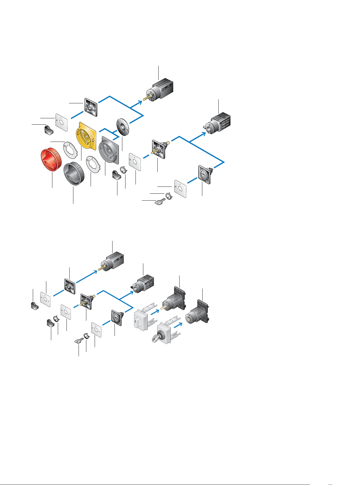
System overview
AUTO
HAND
O
1
0
2
9
3
4
4
4
5
6
6
6
7
7
8
1
9
TM - Control switches
TM Switch-disconnectors
1
2
5
3
4
4
4
6
6
6
7
8
8
8
8
9
8
9
10
8
1. Flush mounting
2.Center mounting
3 and 4 . Key operation for center mounting
5 and 6. Standard switches for center mount-
ing
7 and 8. Control circuit isolators
9 and 10. Standard switches for ush mount-
ing
1. Flush mounting
2.Center mounting
3 and 4 . Key operation for center mounting
5 and 6. Standard switches for center mount-
ing
7 and 8. Standard switches for ush mounting
9. Service distribution board mounting
11
EATON P Switch-disconnectors and T Rotary cam switches CA042001EN
T Rotary Cam switches - Overview
5
6
7
8
8
9
4
3
2
1
9
7
6
5
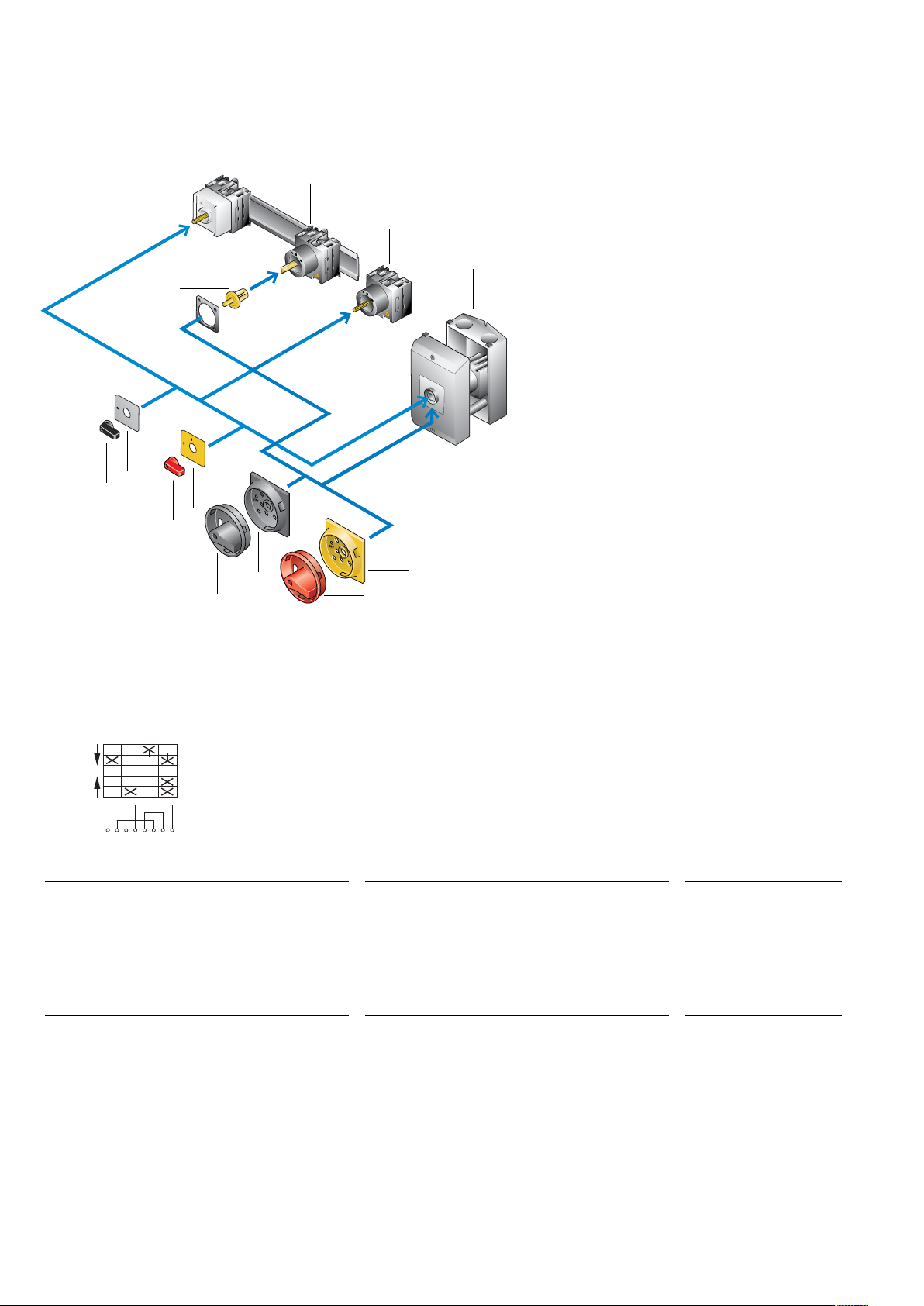
1. Service distribution board mounting
2. Rear mounting
3. Flush mounting
4. Surface mounting
5. Coupling drive
6. Thumb grip
7. Thumb grip for use as emergency switching
o device (not for Control switch)
8. Main switch kit with black handle
9. Main switch kit with red and yellow handle for use as
emergency switch-off
T0, T3, T5B, T5 Switch-disconnectors
System overview
Circuit representation for all T versions
Circuit representation
Switch from 0 to 1
Contact 1 – 2 open,
Contact 3 – 4 open,
Contact 5 – 6 open,
Contact 7 – 8 closed
Switch from 1 to START
with automatic return to 1
Contact 1 – 2 open,
Contact 3 – 4 closed,
Contact 5 – 6 open,
Contact 7 – 8 remains closed
Switch from 1 to 0
Contact 1 – 2 open,
Contact 3 – 4 open,
Contact 5 – 6 open,
Contact 7 – 8 open
Switch from 0 to 2
Contact 1 – 2 closed,
Contact 3 – 4 open,
Contact 5 – 6 open,
Contact 7 – 8 closed
Switch from 2 to START
with automatic return to 2
Contact 1 – 2 open,
Contact 3 – 4 open,
Contact 5 – 6 closes with early make,
Contact 7 – 8 opens with late break
Switch from 2 to 0
Contact 1 – 2 open,
Contact 3 – 4 open,
Contact 5 – 6 open,
Contact 7 – 8 open
1
2
3
4
5
6
7
8
START
1
0
2
START
Links
Terminal markings
Front plate labeling
12
EATON P Switch-disconnectors and T Rotary cam switches CA042001EN