161页面.pdf - 第68页
Rear mounting switch-disconnectors Description Rea r mou nti ng s wi tch - dis con nec to rs c an b e eas ily i ns t alle d, ei the r usin g scre w x ing s or d irec t l y onto a D IN -R ail , on t he rear of a pa nel ,…
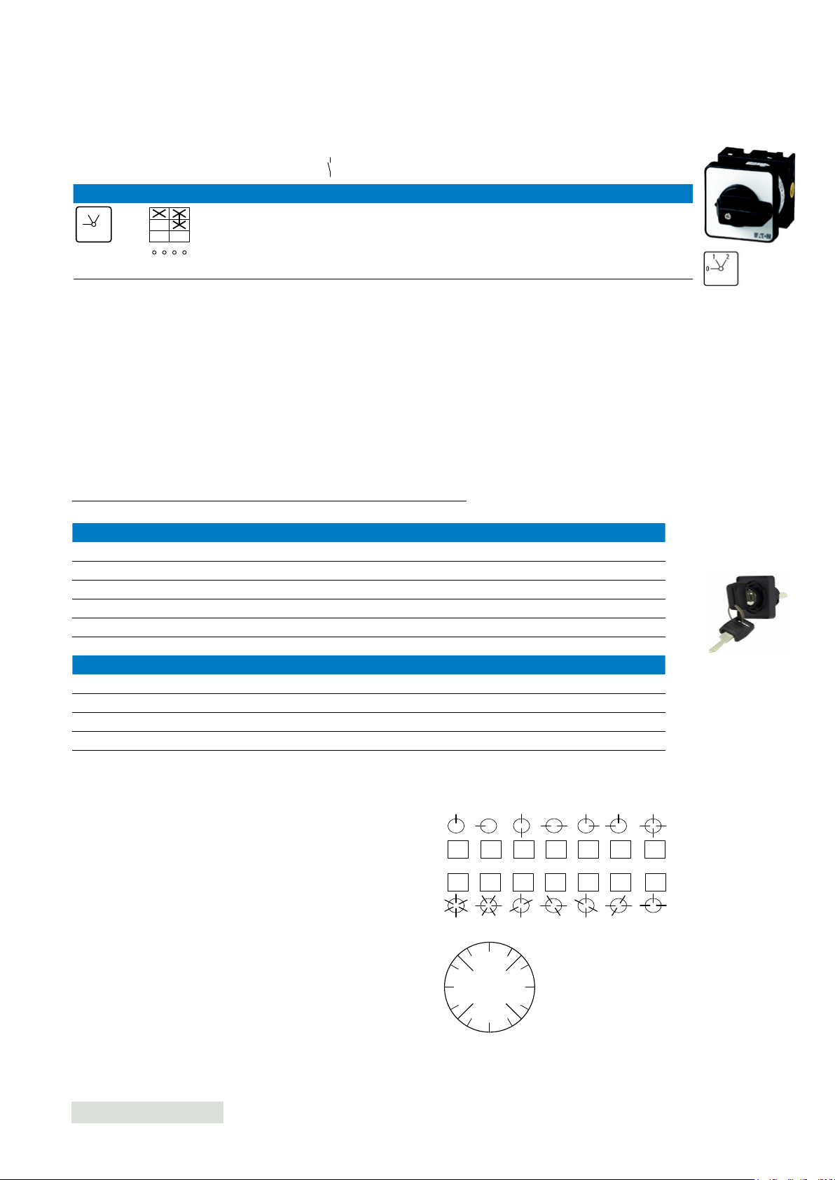
Centre mounting - Step switch-disconnectors for heating
Contact sequence
Number
of poles Suitable for
export to
North America
(US and
Canada)
Padlockable
handleFront plate
Rated
current Part number
Article
number
Pack
qty
With 0 (OFF) position
20 A 1 T0-1-91/EZ 074455 1
X
FS 614
0
21
1
2
3
4
012
074455
N/O
Without emergency switch o/emergency stop function
Photos are representative
For ordering with base switch unit For ordering as a standalone unit
Part number Article number Part number Article number
Key withdrawable in position
Micromec lock 90
o
switch angle
+EZ/S-A 045458 EZ/S-A-TM 046991 0°
+EZ/S-B 045459 EZ/S-B-TM 046992 270°
+EZ/S-E 045462 EZ/S-E-TM 046995 0° + 90°
+EZ/S-F 045463 EZ/S-F-TM 046996 270° & 0°
+EZ/S-G 045464 EZ/S-G-TM 046997 270° + 0° + 90° + 180°
+EZ/S-R 045471 EZ/S-R-TM 047004 270° + 0° + 90°
Ronis lock 60
o
switch angle
+EZ/S-D 045461 X X 270° + 90°
+EZ/S-H 045465 X X 300° + 0° + 60° + 120° +180° + 240°
+EZ/S-J 045466 X X 270° + 330° + 30° + 90° +150° + 210°
+EZ/S-N 045468 X X 270° + 330° + 90° + 150°
Centre mounting dedicated accessories
Key operated lock mechanism
Options for key withdrawal
Position marking as in example
A
BF
E
R
G
C
D
H
J
M
N
P
Q
330
0
30
300
270
240
225
210
180
150
135
120
90
60
315
45
Key operation lock mechanism, incuding. 2 keys.
The key can only be removed in certain positions; see diagram.
The MICROMEC lock for 90° can be used for other switching
angles as well if the key withdrawability characteristics match the
type of switch.
Example: +EZ/S-B can be used with a step switch with a
switching angle of 30° if the key is only to be withdrawable in the
0 position at 270°.
67EATON P Switch-disconnectors and T Rotary cam switches CA042001EN
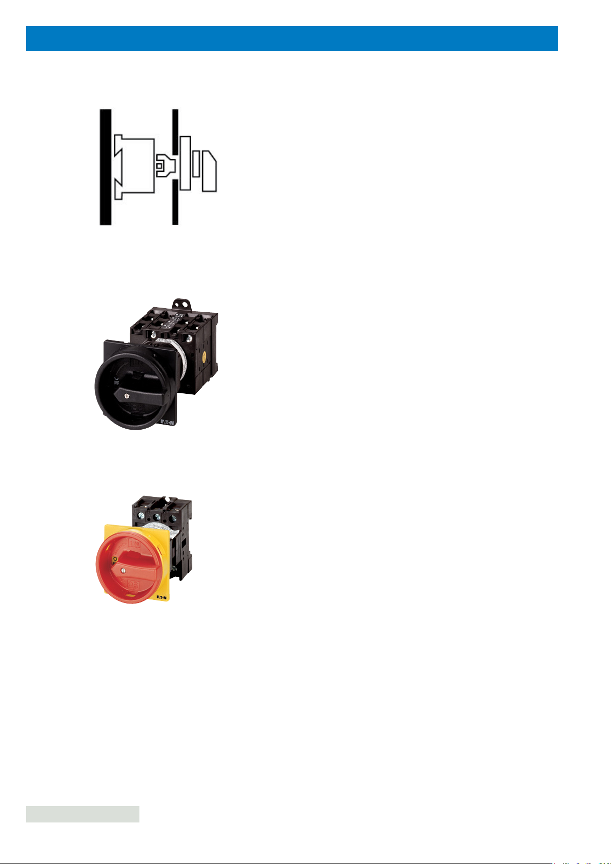
Rear mounting switch-disconnectors
Description
Rear mounting switch-disconnectors can be easily installed,
either using screw xings or directly onto a DIN-Rail, on the rear
of a panel, control board, enclosures in machinery, switchboard
and switchgear.
Standards/Approvals
See details page 178
Technical data
•
Voltage: 690 V a.c.
•
Current: 20 A to 315 A
•
Mounting method: Screw fixings or directly onto a DIN-Rail
Features
•
Available with or without emergency switching off/emergency stop
function
•
Available with and without auxiliary contacts
•
Available with red rotary handle and yellow locking collar and black
rotary handle and locking collar
•
1-pole to 8-pole options
•
T3 Rear mounting
P1 Rear mounting
Photos are representative
68
EATON P Switch-disconnectors and T Rotary cam switches CA042001EN
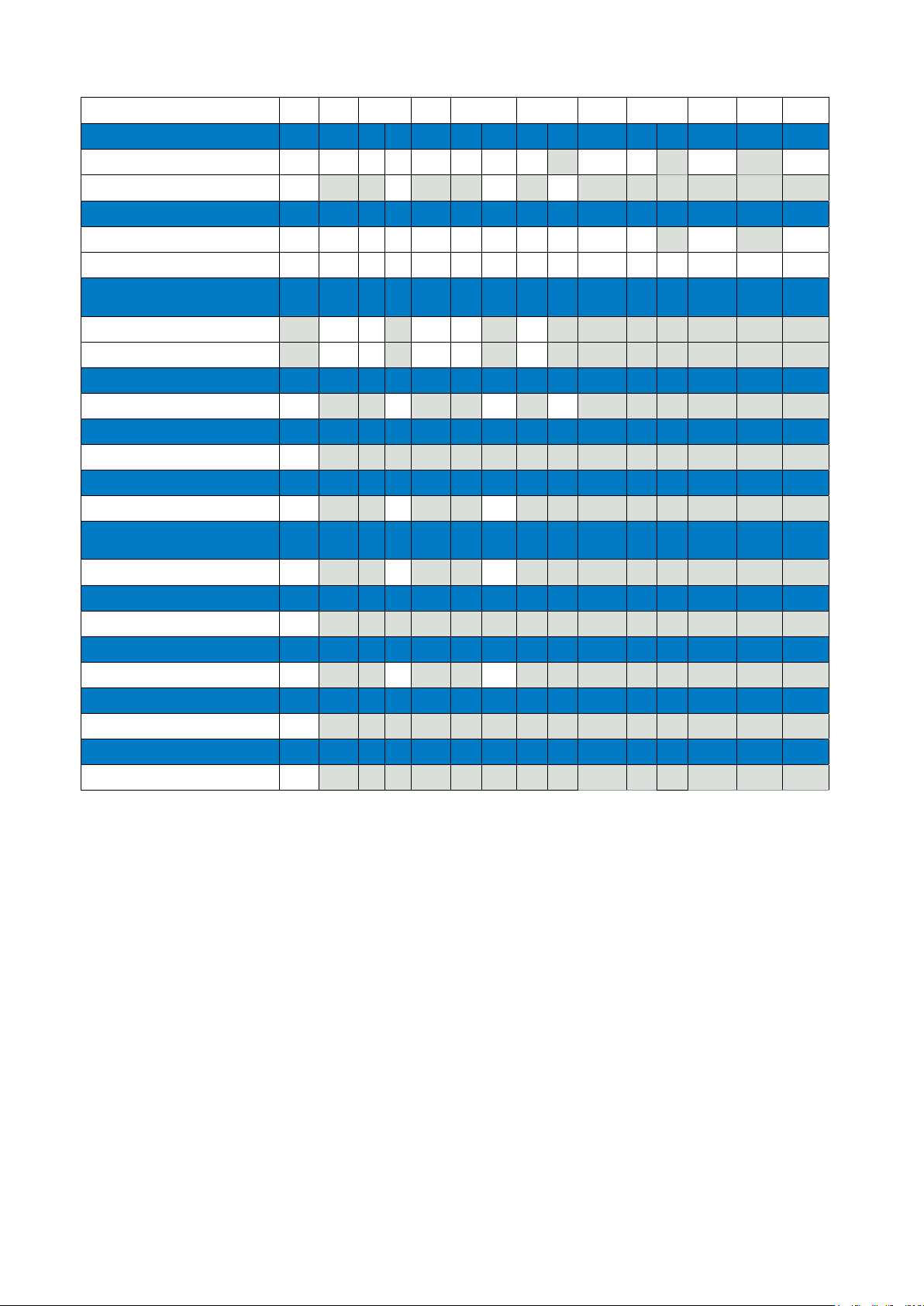
Rear mounting - Range overview
Rated current 20 A 25 A 32 A 40 A 63 A 100 A 125 A 160 A 250 A 275 A 315 A
On-Off switch-disconnectors
T0 P1 P1 T3 P1 P3 T5B P3 T5 P5 P5 T6 P5 P5
Without auxiliary contacts
With auxiliary contacts
Main switch-disconnectors
T0 P1 P1 T3 P1 P3 T5B P3 T5 P5 P5 T6 P5 T8 P5
Without auxiliary contacts
With auxiliary contacts
Main switch-disconnectors
with 400 mm metal shaft extension
P1 P1 T3 P1 P3 P3
Without auxiliary contacts
With auxiliary contacts
Changeover swtich-disconnectors
T0 T3 T5B T5
Without auxiliary contacts
Manual/auto switch-disconnectors
T0
Without auxiliary contacts
Multi speed switch-disconnectors
T0 T3 T5B
Without auxiliary contacts
Reversing speed switch-disconnec-
tors
T0 T3 T5B
Without auxiliary contacts
Selector switch-disconnectors
T0
Without auxiliary contacts
Star-delta switch-disconnectors
T0 T3 T5B
Without auxiliary contacts
Step switch-disconnectors
T0
Without auxiliary contacts
Universal switch-disconnectors
T0
Without auxiliary contacts
69EATON P Switch-disconnectors and T Rotary cam switches CA042001EN