TS5624DMP-User-Guide.pdf - 第10页
10 10. ACCESSORIES 10 .1 FLUID FITTINGS AND TUBING 10 .2 BRACKETS PART NUMBER DESCRIPTION TS918- 46 4-Way Fluid Manifold TN00DKIT Complete Dispensing Tip Kit 9000-000-100 Sample Tip Kit PART NUMBER DESCRIPTION TSD1003- 1…
9
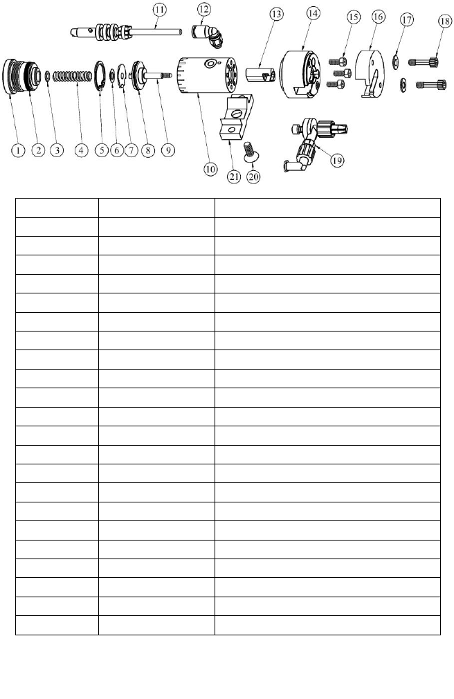
9. SPARE PARTS
ITEM
PART NUMBER
DESCRIPTION
1
5620-000-004
End Cap
2
TSD1400-111APK
End Cap O-Ring (Pack of 10)
3
2800-0892
Washer, SS
4
3300-0578
Spring
5
TSD1120-11
Retaining Ring
6
TSD1109-43
Mylar Washer
7
5620-000-006
Anti-Rotate Washer
8
TSD1400-016APK
Piston O-Ring (Pack of 10)
9
5620-000-005
Piston
10
5620-000-003
Air Cylinder
11
A0100478
Air Hose/Connector Assembly, 4mm
12
TSD1003-20
Air Fitting, 4mm, Elbow
13
7509-0250
Actuator
14
7509-0270
Upper Receiver
15
2800-0463
Upper Receiver Screw
16
7509-0280
Lower Receiver
17
2800-0236
Washer
18
2800-0886
Screw
19
DMP-5624
Disposable Material Path (Pack of 10)
20
TSD1106-13
Mounting Screw
21
918-000-048
Mounting Bracket
22
7509-9100
Syringe Bracket W/Inserts (See Fig.5)
Lubrication: All O-Rings must be lubricated with Bimba HT-99, or equivalent.
Receiver Mounting Screws Torque (Item 18): 14 in lb. (1.58 N-m).
Figure 8.0
10
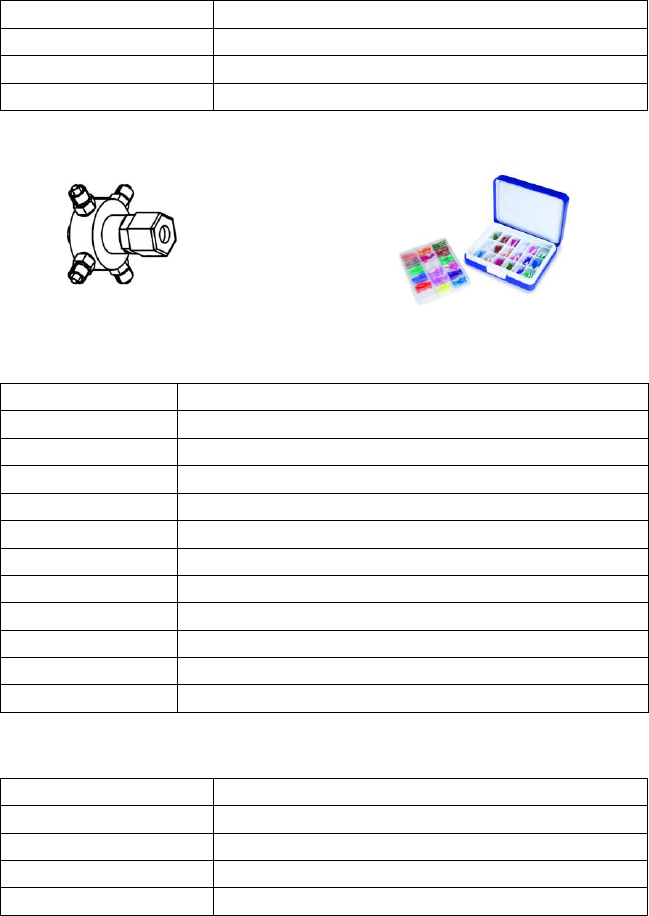
10. ACCESSORIES
10.1 FLUID FITTINGS AND TUBING
10.2 BRACKETS
PART NUMBER
DESCRIPTION
TS918-46
4-Way Fluid Manifold
TN00DKIT
Complete Dispensing Tip Kit
9000-000-100
Sample Tip Kit
PART NUMBER
DESCRIPTION
TSD1003-16
⅛'' NPT to ¼'' O.D. Tube, 90° Elbow
TSD1002-17
⅛'' NPT to ⅜'' O.D. Tube
TSD1002-18
⅛'' NPT to ¼'' O.D. Tube
TSD1002-38
¼'' NPT to ¼'' O.D. Tube
TSD1099-22
⅜'' O.D. X ¼'' I.D. Tube, Black, Polyethylene
TSD1099-23
⅜'' O.D. X ¼'' I.D. Tube, Clear, Polyethylene
TSD1099-24
¼'' O.D. X ⅛'' I.D. Tube, Clear, Polyethylene
TSD1099-25
¼'' O.D. X ⅛'' I.D. Tube, Black, Polyethylene
TSD1099-45
6mm O.D. X 4mm I.D, Clear, Polyethylene
TSD1099-46
6mm O.D. X 4mm I.D, Black, Polyethylene
TSD126-360BPK
Luer Lock Tubing, 60'' (1524mm) , Black
PART NUMBER
DESCRIPTION
918-033-000
Productions Master Stand (Base & Support)
918-000-012
Rod Clamp Assembly
5620-000-008
4'' (101.6mm) Threaded Mounting Rod
7509-9100
Syringe Bracket With Inserts

11
11. TROUBLE SHOOTING
PROBLEM
POSSIBLE CAUSE
CORRECTION
No fluid flow
Fluid pressure too low
Increase fluid pressure
Operating pressure too low
Increase air pressure to 70 psi
(4.8bar)
Dispense tip clogged
Replace tip
Fluid cured in valve chamber
Replace material path
Stroke adjustment closed
Open stroke adjustment
counterclockwise
Inconsistent
fluid flow
Fluid pressure fluctuating
Ensure fluid pressure is
constant
Valve operating pressure is too
low
Increase valve pressure to 70
psi (4.8bar)
Valve open time is not
consistent
Check to make sure the valve
controller is providing a
consistent output
Air trapped in fluid housing
Purge valve
Fluid drools after
the valve closes,
eventually
stopping
Air trapped in fluid chamber
Purge valve
Steady drip
Worn material path
Replace material path
Fluid pressure exceeds 60 psi
(4.1bar)
Lower fluid pressure