TS5624DMP-User-Guide.pdf - 第7页
7 7. DISPOSABLE M ATERIAL PATH REM OVAL/REPLACEM ENT: Removal of a feed path assembly: Refer to figure 6 .0 1. Release fluid p ressure. 2. Remove syringe barrel or fluid line from the valv e. 3. Loosen th e lower receive…
6
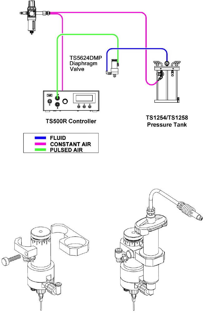
6. TYPICAL SYSTEM SET-UP
Figure 4.0
Figure 5.0
Optional Syringe Feeding
1. Attach 7509-9100 syringe bracket as shown below.
2. Use insert rings for syringe sizes 3cc – 10cc.
3. Ensure syringe is under constant air pressure.
7
7. DISPOSABLE MATERIAL PATH REMOVAL/REPLACEMENT:
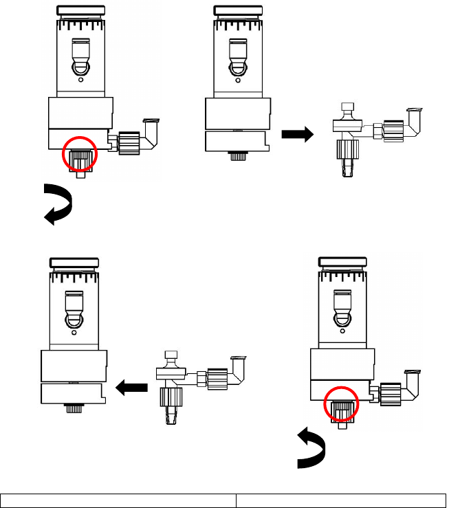
Removal of a feed path assembly: Refer to figure 6.0
1. Release fluid pressure.
2. Remove syringe barrel or fluid line from the valve.
3. Loosen the lower receiver screws (4 - 5 turns) and pull out disposable material
path.
4. Dispose of the used feed path assembly in an appropriate waste container.
Installation of a new feed path assembly: Refer to figure 6.0
1. Insert a new feed path assembly into the valve housing. Ensure correct fitment
into the actuator.
2. Tighten lower receiver screws to torque setting specified below.
Torque Specifications
14 in lb. (1.58 N-m)
Figure 6.0
1. Loosen screws
4 - 5 turns.
2. Remove DMP
insert.
3. Insert new
DMP insert.
4. Tighten screws
evenly to torque
setting.
8
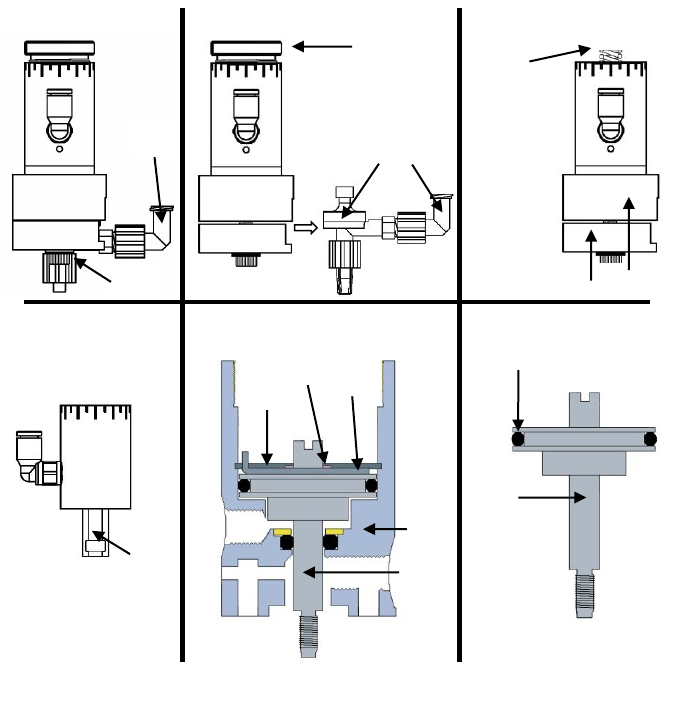
8. MAINTENANCE OF AIR CYLINDER O-RING (Refer to figure 7.0 and 8.0)
1. Unscrew receiver screws (1).
2. Remove the DMP (2).
3. Remove the stroke control knob (3) and spring (4).
4. Remove the receiver assembly (5).
5. Remover actuator (6).
6. Remove retaining ring (7), anti-rotate washer (8) and Mylar washer (9).
7. Remove piston (10) from air cylinder (11).
8. Replace O-ring (12) if damaged; otherwise lubricate O-ring with Bimba
HT-99, or equivalent.
9. Reinstall piston (10), retaining ring (7), anti-rotate washer (8) and Mylar
washer (9).
10. Reinstall actuator (6) as per position in Step 4. 90° offset to the air inlet.
11. Reinstall receiver assembly (5), leaving receiver screws loose.
12. Reinstall spring (4) and stroke control knob (3).
13. Install DMP (2) and set torque on receiver screws. - 14 in lb. (1.58 N-m)
Vertical slot must
face this way, 90°
offset to the air inlet.
Step 1
Figure 7.0
(12)
(10)
(1)
(2)
(2)
(3)
(4)
(5)
(6)
(7)
(8)
(10)
(11)
(9)
Step 2
Step 3
Step 6
Step 5
Step 4