TS5624DMP-User-Guide.pdf - 第5页
5 5. SETUP INSTRUCTIONS Refer to Figure 3 .0 Note: This installation uses Luer lock adapters shipped with the valve. 1. Connect the fluid feed tube or syringe to the fluid inlet port (1 ). 2. Connect the valve airline to…
4
2. UNPACKING AND INSPECTION
Carefully unpack the valve and examine the items contained in the carton. These
will include:
Valve assembly.
Mounting bracket and mounting screw.
1 x Disposable Material Path.
2 x Hex keys (1/8” & 9/64”).
Sample tip kit.
Fluid line and air hose.
User guide.
3. DESCRIPTION
The TS5624DMP Diaphragm Valve is designed to dispense low to medium
viscosity fluids. An internal spring return makes the valve fully adaptable for use
with any time/pressure controller. A short opening stroke provides extremely fast,
positive shut-off. An external stroke control adjustment makes it easy to fine tune
shot sizes. The TS5624DMP Diaphragm Valves compact design allows for
mounting flexibility and easy integration into automated applications.
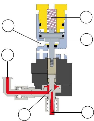
4. THEORY OF OPERATION (Refer to figure 2.0)
The TS5624 Diaphragm Valve is normally closed, adjustable stroke valve. Input
air pressure of 70-90 psi (4.8 to 6.2bar) through air inlet port (1) drives the piston
assembly (2) back, opening the material path, allowing fluid flow from the
material inlet (3) to the material outlet (4). Relieving the input air pressure allows
the piston return spring (5) to close the diaphragm (6), ensuring rapid “fail-safe”
shut-off of fluid flow.
Figure 2.0
3
1
6
2
5
4
5
5. SETUP INSTRUCTIONS
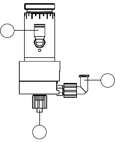
Refer to Figure 3.0
Note: This installation uses Luer lock adapters shipped with the valve.
1. Connect the fluid feed tube or syringe to the fluid inlet port (1).
2. Connect the valve airline to the valve controller or other pneumatic device
that is used to control the valve.
3. Connect the opposite end of the airline to valve air inlet (2).
4. Connect appropriate dispensing tip or nozzle to the fluid outlet port (3).
5. Set the valve controller pressure at 70 psi (4.8bar).
6. Set the fluid pressure. Do not exceed 60 psi (4.1bar).
7. Make sure all connections are tight.
8. Place container under the outlet and activate the valve until the fluid flows
steady.
The amount of fluid that flows through the valve is determined by:
Valve open time
Fluid reservoir pressure
Dispensing tip size
Stroke adjustment knob position
Figure 3.0
1
3
2
6
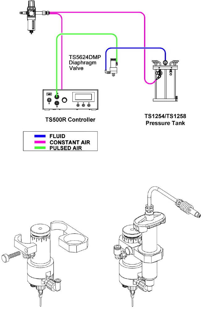
6. TYPICAL SYSTEM SET-UP
Figure 4.0
Figure 5.0
Optional Syringe Feeding
1. Attach 7509-9100 syringe bracket as shown below.
2. Use insert rings for syringe sizes 3cc – 10cc.
3. Ensure syringe is under constant air pressure.