SOM-1740-001.pdf - 第13页
12 Tg0934-PM-SO 0310-001

11 Tg0934-PM-SO0310-001
6.2 Recovery Procedure from Error Display
(7) Restore the "Emergency Stop" condition.
Refer to "Volume 1, Section 4, 3.1 [EMERGENCY STOP] Switch
Pressed" in the instruction manual for the Main Machine on how to
reset the [Emergency Stop] switch.

12 Tg0934-PM-SO0310-001
13 Tg0934-PM-SO0310-001-(M696JSC-A1004)
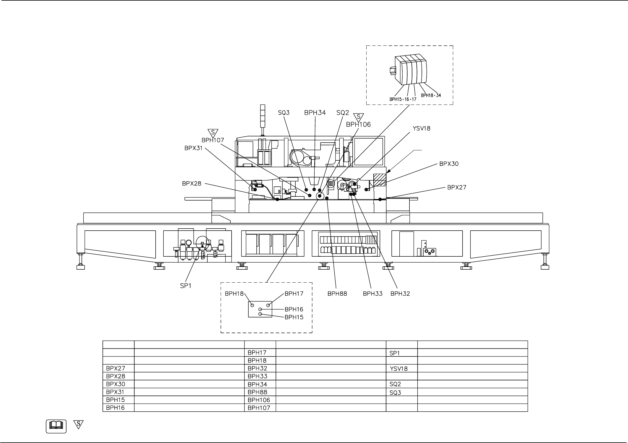
7. Materials
UA54(H1)
Layout of Amplifier Unit
Layout of Sensor Section
Light Receiving Side
Disengaged Feeder Latch Detection (F12 Side)
Disengaged Feeder Latch Detection (F34 Side)
Feeder Installation Error Detection (F12 Side)
Feeder Installation Error Detection (F34 Side)
Nozzle Lower Limit Error
Nozzle Level Detection
Unrequired Nozzle #1
Unrequired Nozzle #2
Cutter Forward Limit
Cutter Backward Limit
Tape End Detection
Nozzle Change / Return
Pick-Up Miss Check A
Pick-Up Miss Check B
Air Pressure Drop Detection
Nozzle Change/Return Stopper
Lifted Feeder Prevention Detection (F12 Side)
Lifted Feeder Prevention Detection (F34 Side)
Symbol SymbolSymbolName Name Name
-marked area is specially specified.
Note
7. Materials
7.1 Layout of Sensors and Loads
Layout of Sensors and Loads (Rear Side of Main Machine)