SOM-1740-001.pdf - 第16页
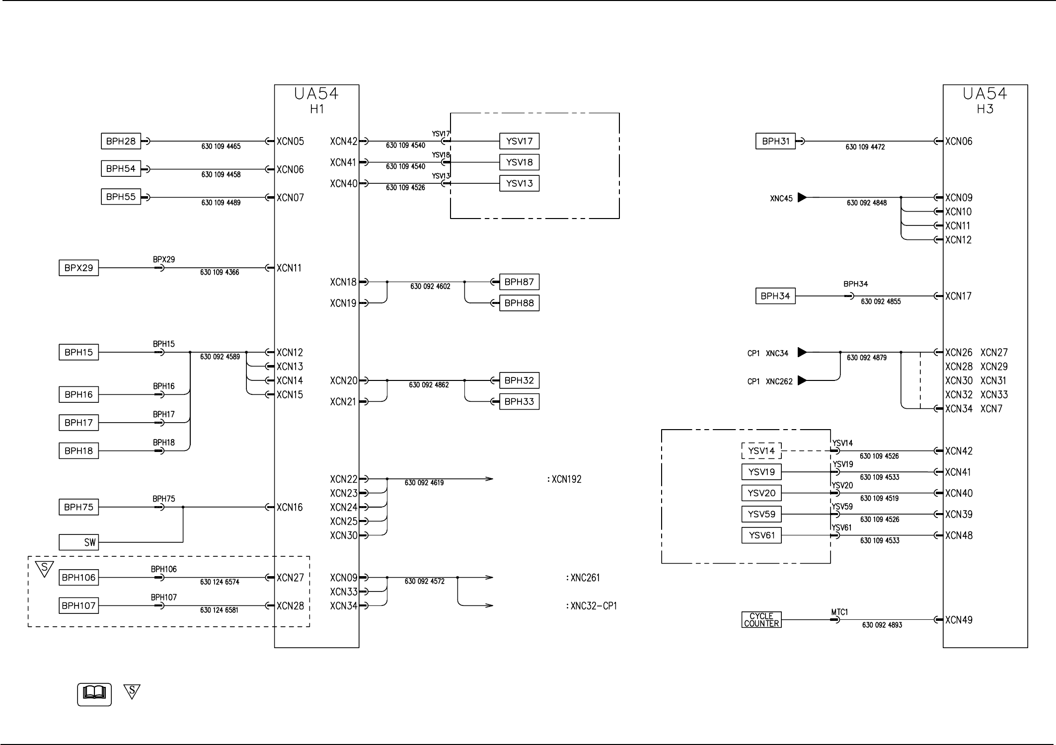
15 Tg0934-PM-SO 7.3 Cord Connection Diagram 7.3 Cord Connection Diagram Cord Connection Diagram (H1/H3 Boards) 0310-001-(M696JSB-A1008) Rotary Slip Ring Head Section Head Section Rear Operation Panel Head Section Head Se…
14 Tg0934-PM-SO0310-001-(M696WD--A1003)
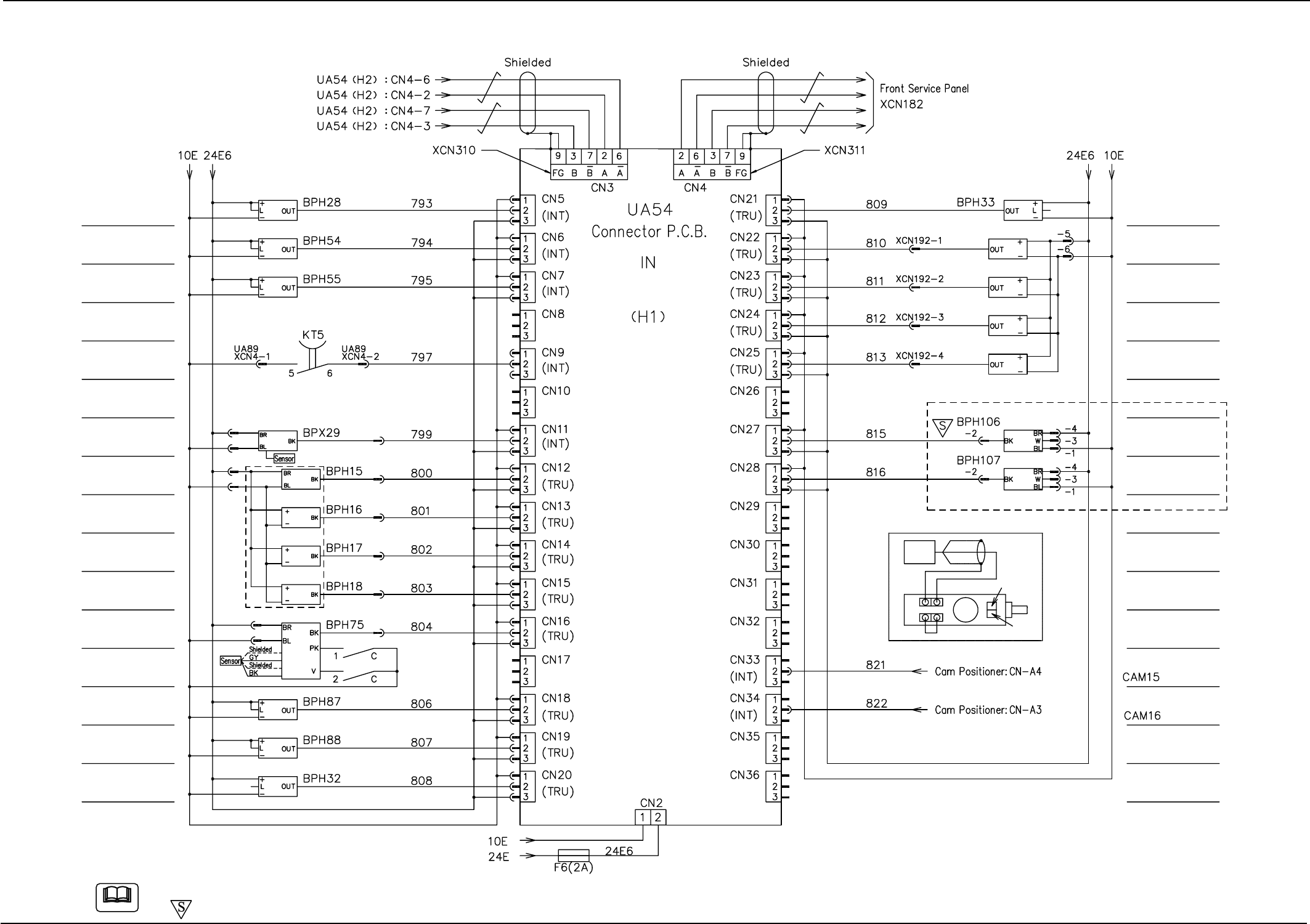
7.2 Electrical Circuit Diagram
7.2 Electrical Circuit Diagram
I/O Board H1 1/2
Note
Placement Interlock
Cam Phase Check A
Cam Phase Check B
Rotary Turret Wheel
Handle Check
Low Nozzle Detection
Nozzle Lower Limit
Error
Nozzle Level Detection
Unrequired Nozzle 1
Unrequired Nozzle 2
Bad Mark Detection
Nozzle Change
Nozzle Change/Return
Cutter Forward
Movement Check
Cutter Backward
Movement Check
Head No. Detection 1
Head No. Detection 2
Head No. Detection 3
Head No. Detection 4
Pick-Up Miss Check A
Pick-Up Miss Check B
Sensors in Slip Ring Section
Note (c)
Note (c)
Note (a)
Note (b) Integrated power line
Rotary Switch
Amplifier
Shield Core Cable
Operation
Selector
Timer
Sensor
Note (a)
(c) Connect connectors so that the drain line is connected to terminal 9 of the connector and the shield section is connected to the connector body for grounding respectively.
(d)
-marked area is specially specified.
15 Tg0934-PM-SO
7.3 Cord Connection Diagram
7.3 Cord Connection Diagram
Cord Connection Diagram (H1/H3 Boards)
0310-001-(M696JSB-A1008)
Rotary
Slip Ring
Head Section
Head Section
Rear Operation Panel
Head Section
Head Section
-marked area is specially specified.
Note

16 Tg0934-PM-SO0310-001